 Technical datasheet
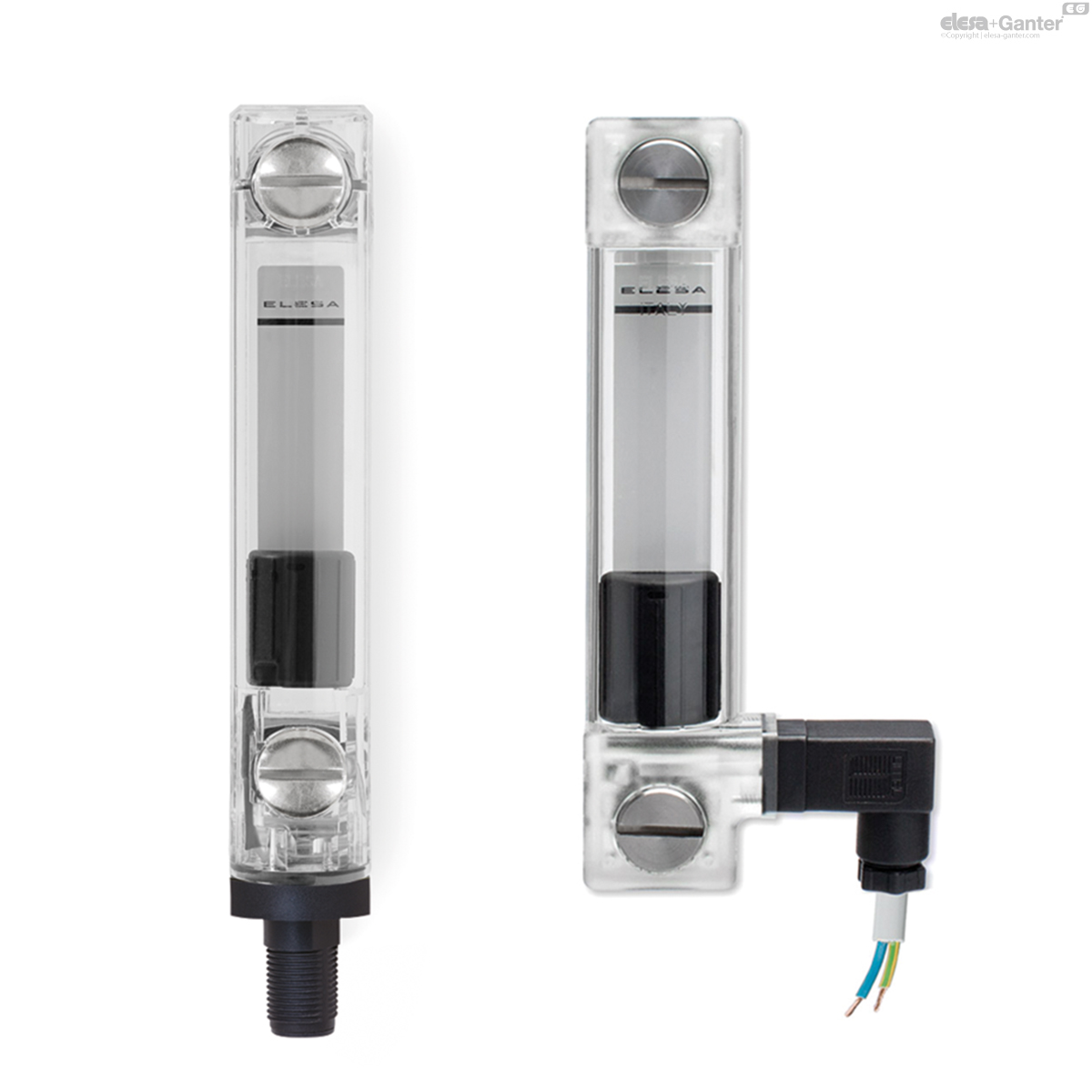
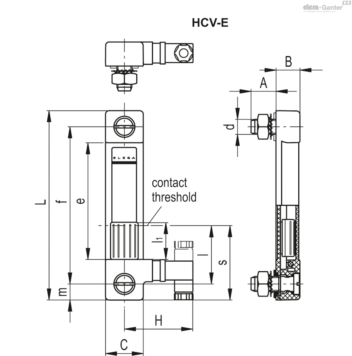
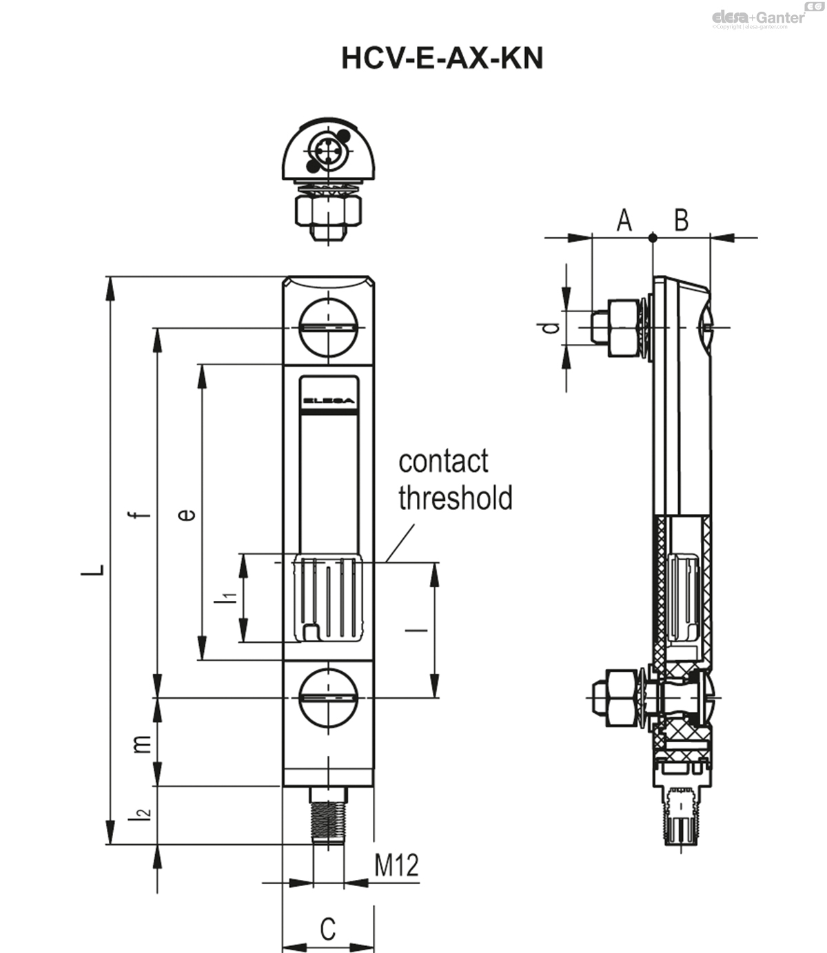
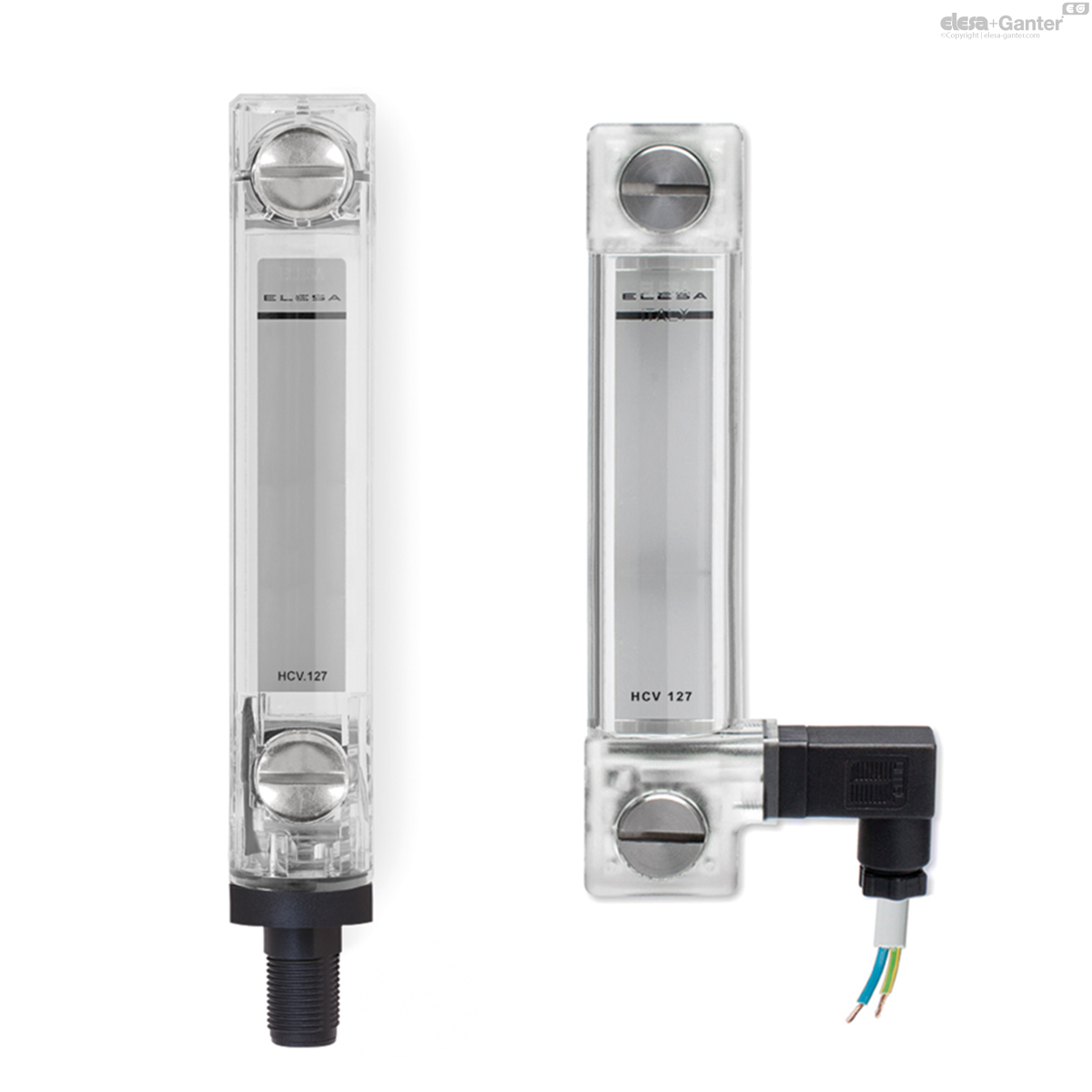
HCV-EElektrische oliepeilglazen
Elektrische oliepeilglazen
met MIN-niveausensor

|
Code
|
Omschrijving
|
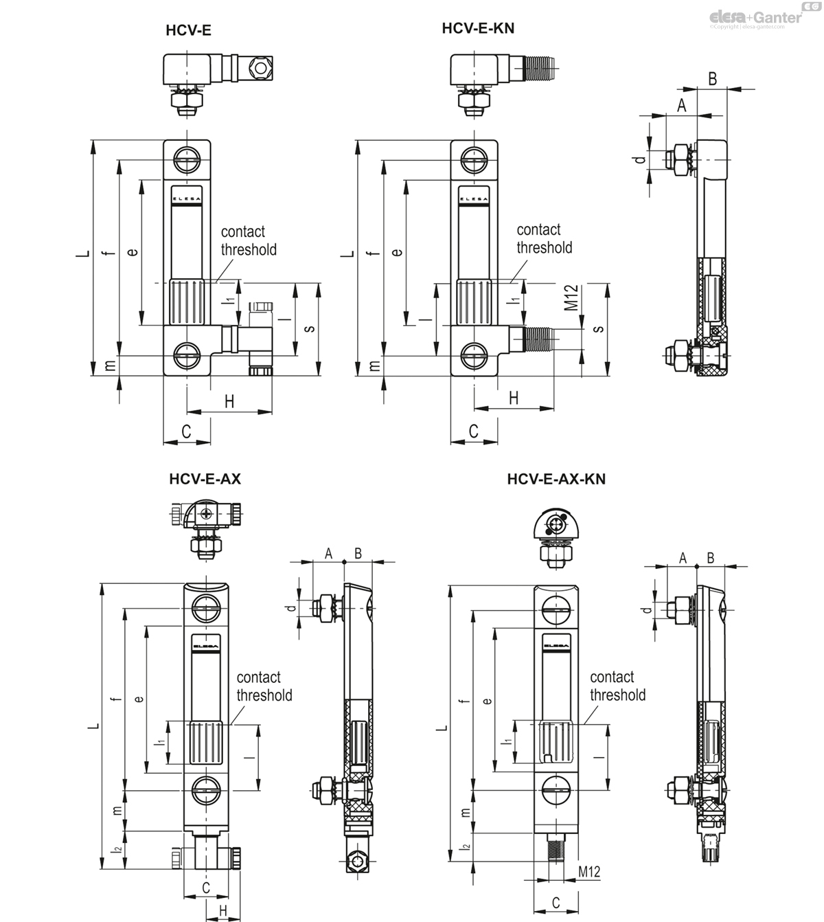
f
|
d
|
A
|
B
|
C
|
H
|
L
|
e
|
l
|
l1
|
l2
|
|---|---|---|---|---|---|---|---|---|---|---|---|---|
|
|
|
|
|
|
|
|
|
|
|
|
|
|
|
11051
|
HCV.76-E-NO-M10
|
76
|
M10
|
20
|
19.5
|
30.5
|
55
|
102
|
43.5
|
40
|
20
|
-
|
|
11182
|
HCV.127-E-AX-NC-M12
|
127
|
M12
|
21.8
|
20
|
31
|
25.5
|
201.5
|
97
|
50
|
30
|
29
|
|
11053
|
HCV.76-E-SW-M10
|
76
|
M10
|
20
|
19.5
|
30.5
|
55
|
102
|
43.5
|
40
|
20
|
-
|
|
11181
|
HCV.127-E-AX-NO-M12
|
127
|
M12
|
21.8
|
20
|
31
|
25.5
|
201.5
|
97
|
50
|
30
|
29
|
|
11052
|
HCV.76-E-NC-M10
|
76
|
M10
|
20
|
19.5
|
30.5
|
55
|
102
|
43.5
|
40
|
20
|
-
|
|
11183
|
HCV.127-E-AX-SW-M12
|
127
|
M12
|
21.8
|
20
|
31
|
25.5
|
201.5
|
97
|
50
|
30
|
29
|
|
11132
|
HCV.127-E-NC-M12
|
127
|
M12
|
20
|
19.5
|
30.5
|
55
|
153
|
97
|
50
|
30
|
-
|
|
11133
|
HCV.127-E-SW-M12
|
127
|
M12
|
20
|
19.5
|
30.5
|
55
|
153
|
97
|
50
|
30
|
-
|
|
11131
|
HCV.127-E-NO-M12
|
127
|
M12
|
20
|
19.5
|
30.5
|
55
|
153
|
97
|
50
|
30
|
-
|
|
11135
|
HCV.254-E-NO-M12
|
254
|
M12
|
20
|
19.5
|
30.5
|
55
|
280
|
224
|
50
|
30
|
-
|
|
11136
|
HCV.254-E-NC-M12
|
254
|
M12
|
20
|
19.5
|
30.5
|
55
|
280
|
224
|
50
|
30
|
-
|
|
11137
|
HCV.254-E-SW-M12
|
254
|
M12
|
20
|
19.5
|
30.5
|
55
|
280
|
224
|
50
|
30
|
-
|
|
11051-KN
|
HCV.76-E-NO-M10-KN
|
76
|
M10
|
20
|
19.5
|
30.5
|
47
|
102
|
43.5
|
40
|
20
|
-
|
|
11052-KN
|
HCV.76-E-NC-M10-KN
|
76
|
M10
|
20
|
19.5
|
30.5
|
47
|
102
|
43.5
|
40
|
20
|
-
|
|
11053-KN
|
HCV.76-E-SW-M10-KN
|
76
|
M10
|
20
|
19.5
|
30.5
|
47
|
102
|
43.5
|
40
|
20
|
-
|
|
11131-KN
|
HCV.127-E-NO-M12-KN
|
127
|
M12
|
20
|
19.5
|
30.5
|
47
|
153
|
97
|
50
|
30
|
-
|
|
11132-KN
|
HCV.127-E-NC-M12-KN
|
127
|
M12
|
20
|
19.5
|
30.5
|
47
|
153
|
97
|
50
|
30
|
-
|
|
11133-KN
|
HCV.127-E-SW-M12-KN
|
127
|
M12
|
20
|
19.5
|
30.5
|
47
|
153
|
97
|
50
|
30
|
-
|
|
11135-KN
|
HCV.254-E-NO-M12-KN
|
254
|
M12
|
20
|
19.5
|
30.5
|
47
|
280
|
224
|
50
|
30
|
-
|
|
11136-KN
|
HCV.254-E-NC-M12-KN
|
254
|
M12
|
20
|
19.5
|
30.5
|
47
|
280
|
224
|
50
|
30
|
-
|
|
11137-KN
|
HCV.254-E-SW-M12-KN
|
254
|
M12
|
20
|
19.5
|
30.5
|
47
|
280
|
224
|
50
|
30
|
-
|
|
11181-KN
|
HCV.127-E-AX-NO-M12-KN
|
127
|
M12
|
21.8
|
20
|
31
|
-
|
194.5
|
97
|
50
|
30
|
20
|
|
11182-KN
|
HCV.127-E-AX-NC-M12-KN
|
127
|
M12
|
21.8
|
20
|
31
|
-
|
194.5
|
97
|
50
|
30
|
20
|
|
11183-KN
|
HCV.127-E-AX-SW-M12-KN
|
127
|
M12
|
21.8
|
20
|
31
|
-
|
194.5
|
97
|
50
|
30
|
20
|
# Maximum tightening torque.
Material
Transparent polyamide based (PA-T) technopolymer. Highly resistant to shocks, solvents, oils with additives, aliphatic and aromatic hydrocarbons, petrol, naphtha, phosphoric esters.
Avoid contact with alcohol or detergents containing alcohol.
Screws, nuts and washers
Zinc-plated steel.
Packing rings
Step-shaped for the seal on the reservoir walls and NBR synthetic rubber O-ring screw underhead.
Suggested roughness of the packing ring application surface Ra = 3 µm.
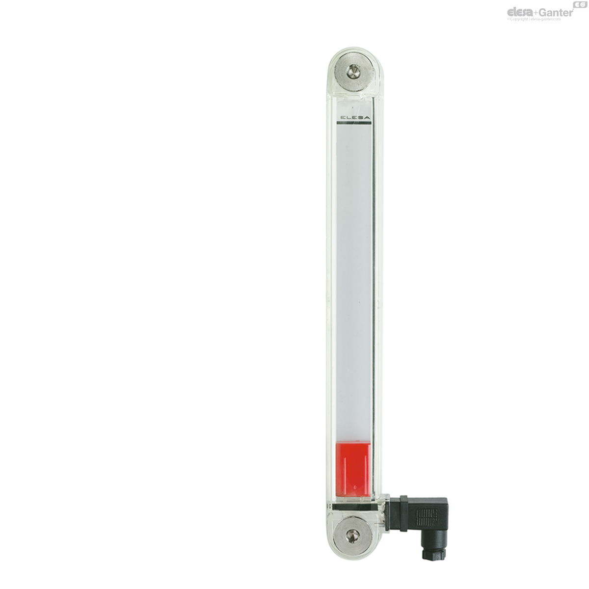
Float
Glass-fibre reinforced polyamide based (PA) technopolymer, black colour, with a built-in magnetic element to activate the electric contact when the float reaches the contact threshold indicated in the drawing (data referred to mineral oil type CB68, according to ISO 3498, temperature 23°C).
Floating is ensured by fluids with densities higher than 800 kg/m3.
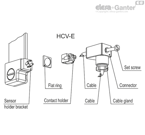
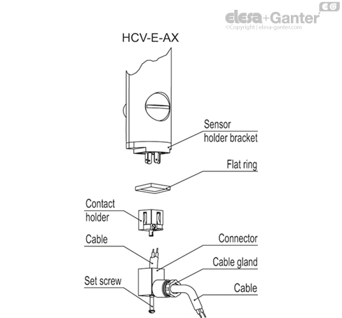
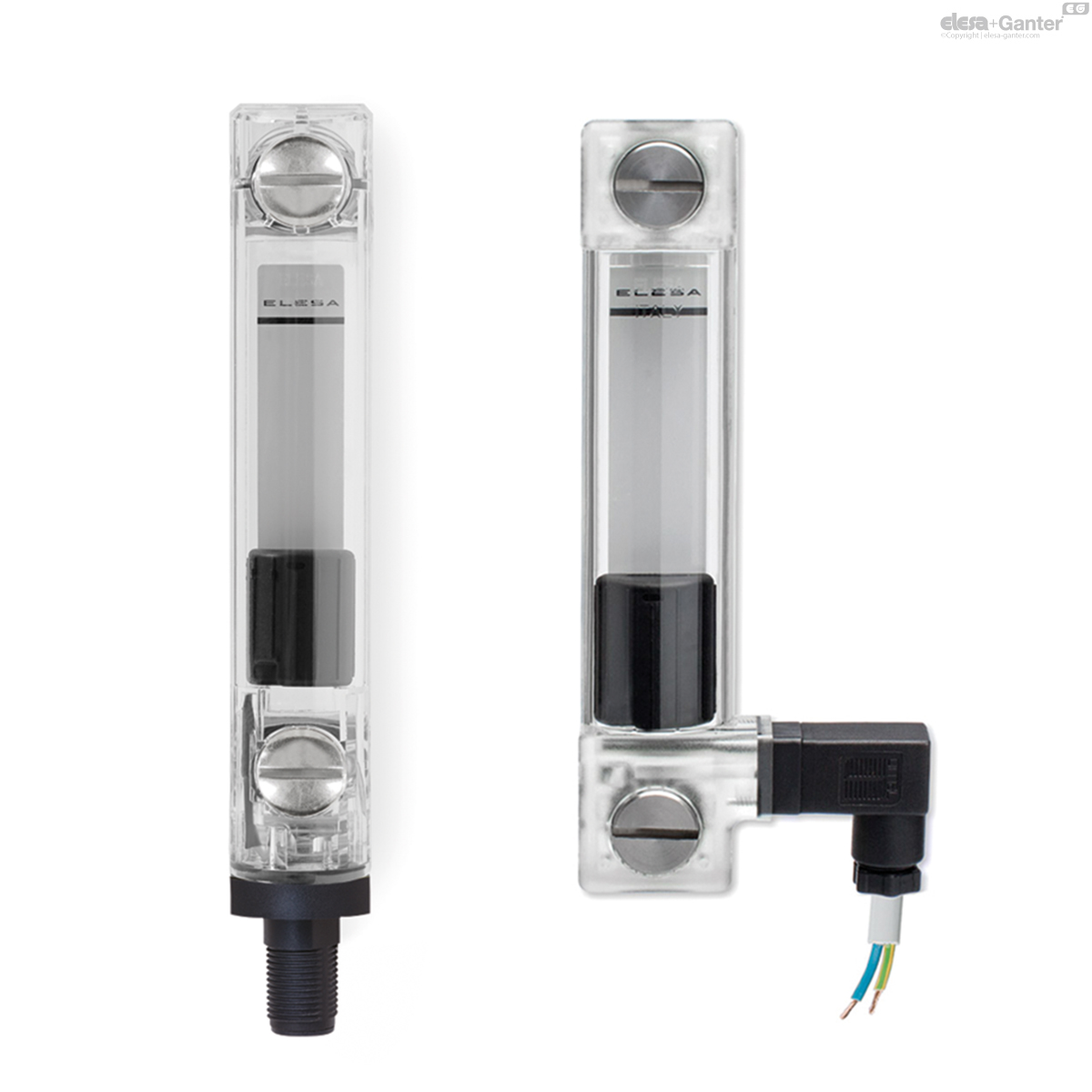
Bracket with male connector
Perfectly watertight, incorporating the relay (reed) with two output conductors (NO and NC version) or three conductors (SW version).
- DIN 43650 C connector in glass-fibre reinforced polyamide based (PA) technopolymer, black colour.
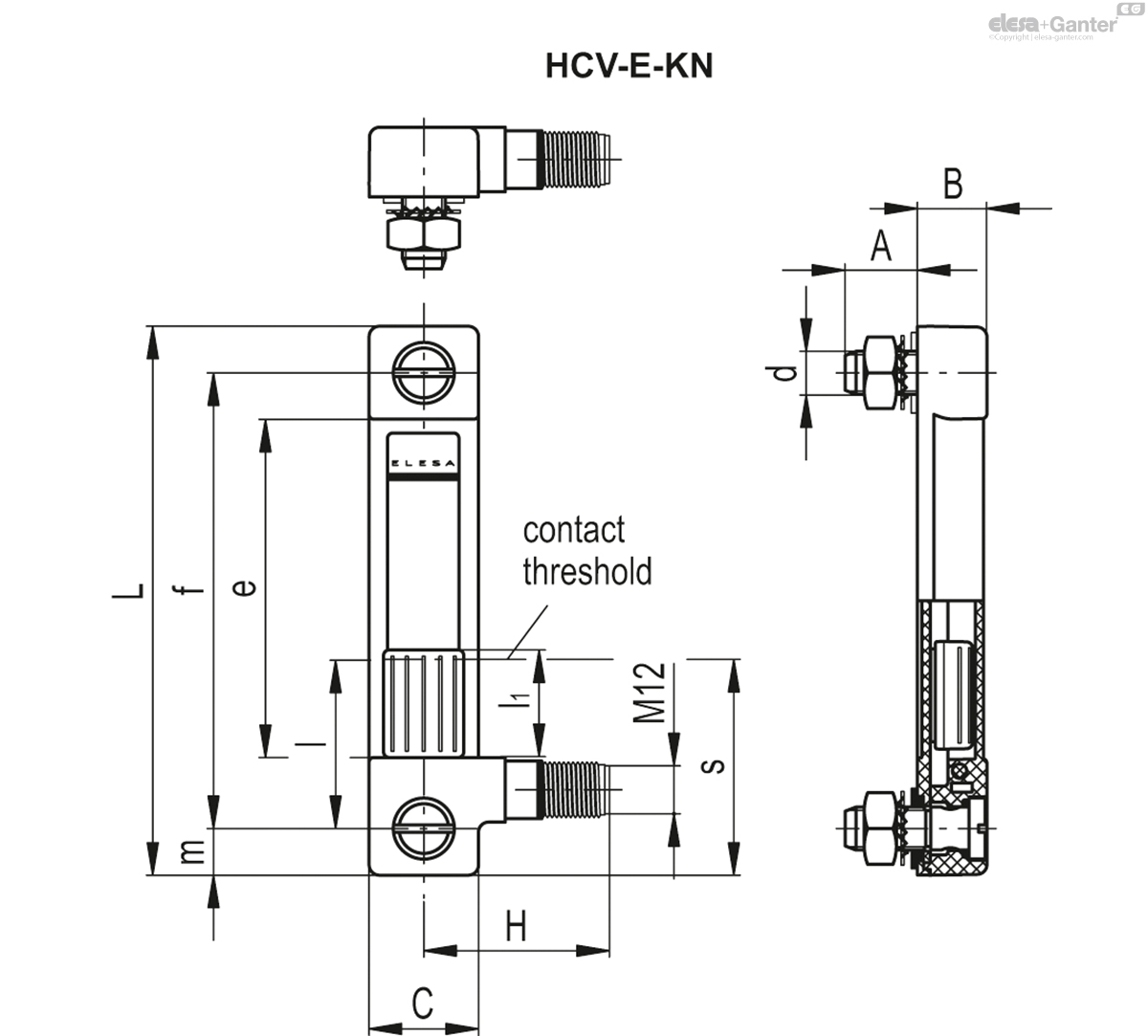
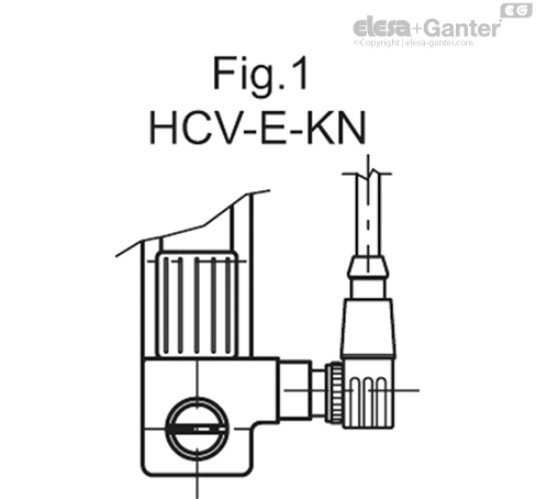
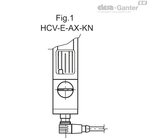
- 4-pole M12x1 connector, with threading in glass-fibre reinforced polyamide based (PA) technopolymer certified self-extinguishing UL-94-V0, black colour, matte finish.
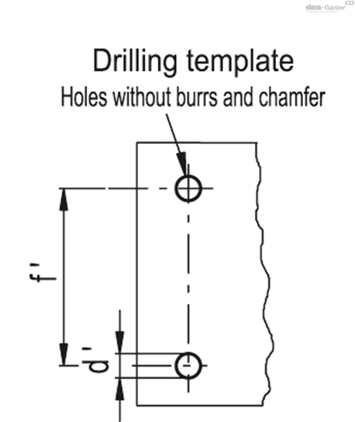
For a correct assembly see Warnings.
Female connector (DIN 43650 C)
With built-in cable gland and contact holder. Front or axial output (high or low) ensuring protection against water sprays (protection class IP 65 according to table EN 60529).
Contrast screen
White lacquered aluminium. The housing, in the appropriate external rear slot, guarantees the best protection from direct contact with fluid.
It can be taken out from the inclined side, before assembly to allow the insertion of level lines or words.
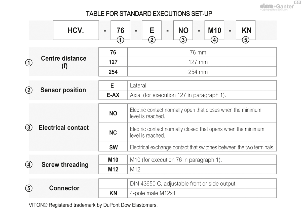
Standard executions
See configuration table.
Maximum continuous working temperature
90°C (with oil).
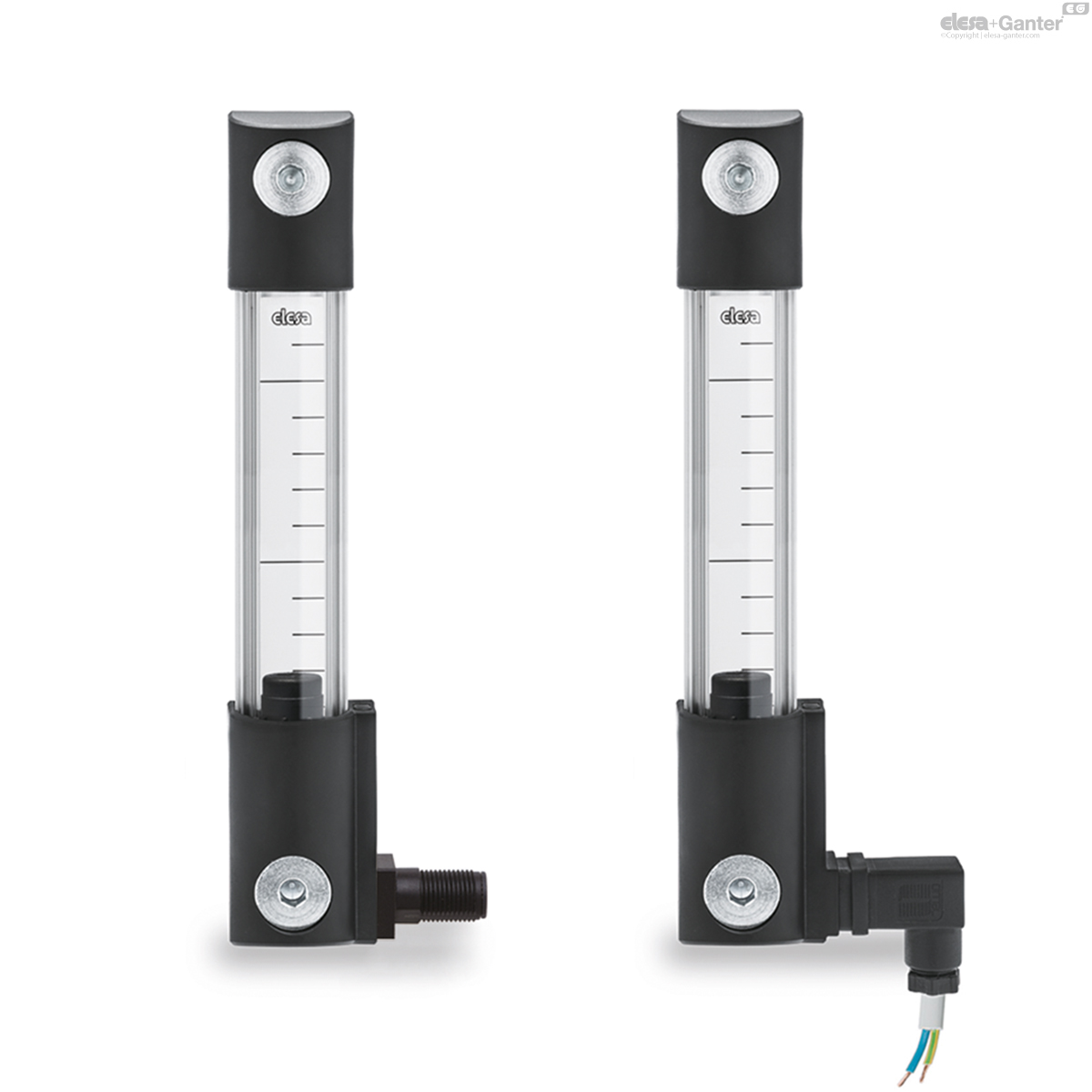
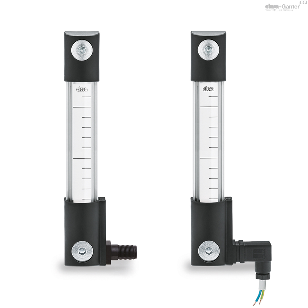
Features and performances
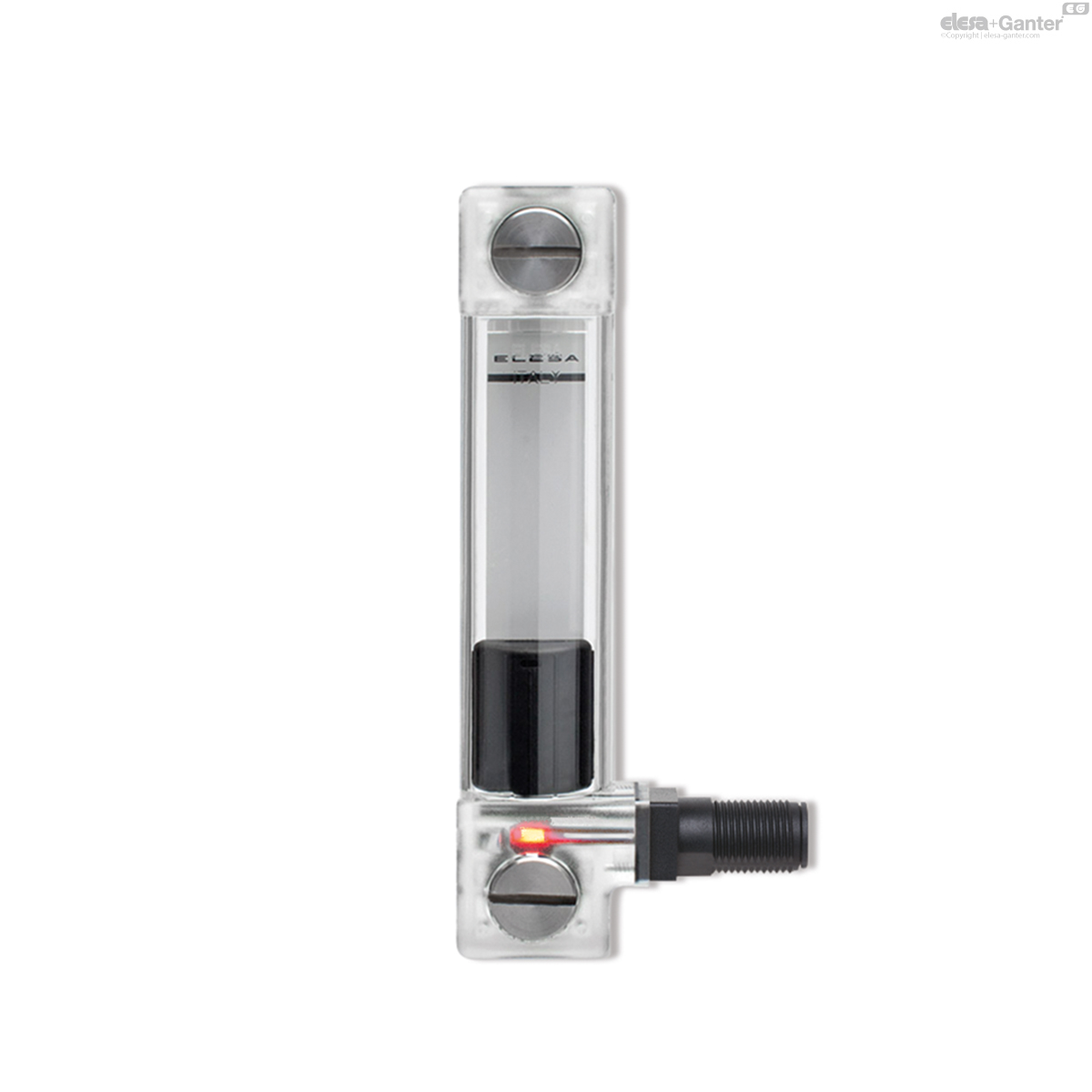
The HCV-E level indicators, in addition to the visual level indicator, also provide an electrical signal when the minimum fluid level value is reached.
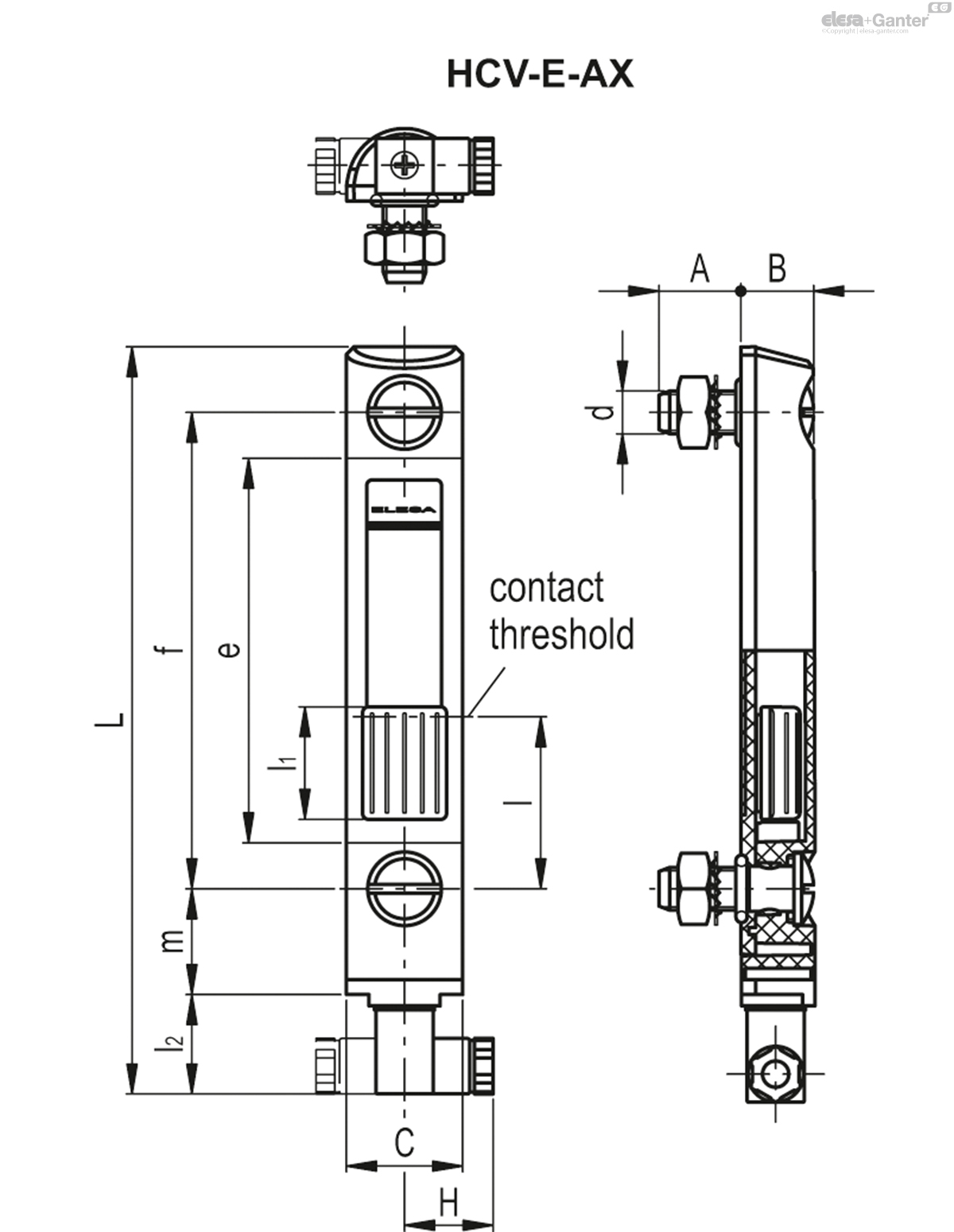
The lateral connector output allows the level of intervention of the sensor to be minimised.
Ultrasound welding to guarantee a perfect seal.
Maximum fluid level visibility even from side positions.
Lens effect for a better visibility of the fluid level.
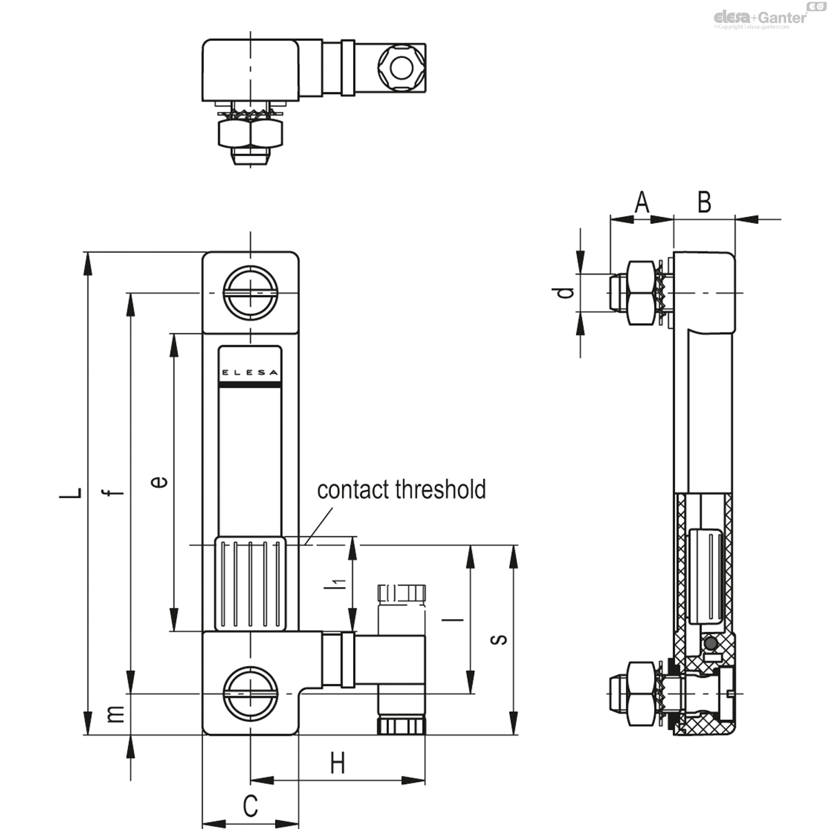
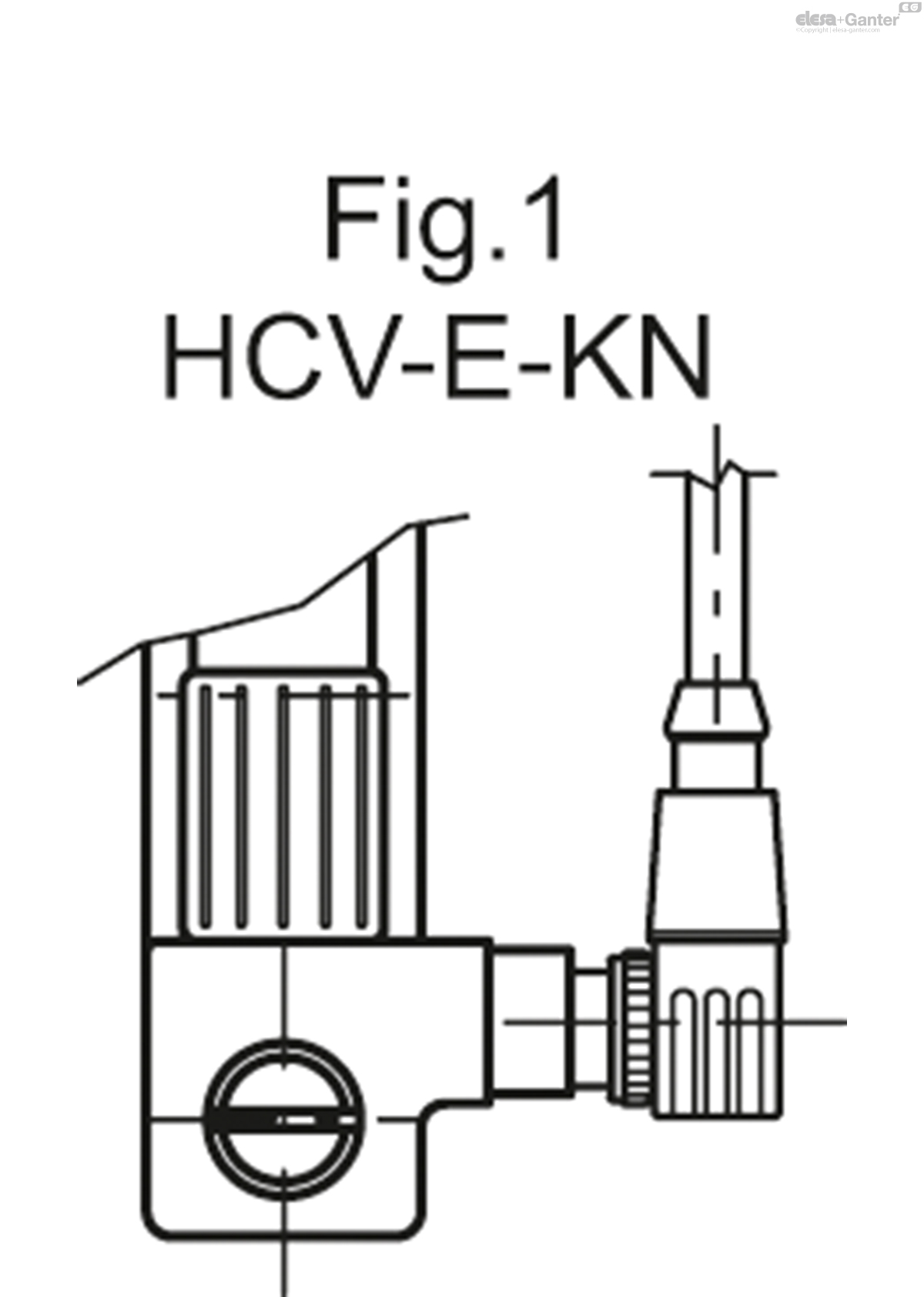
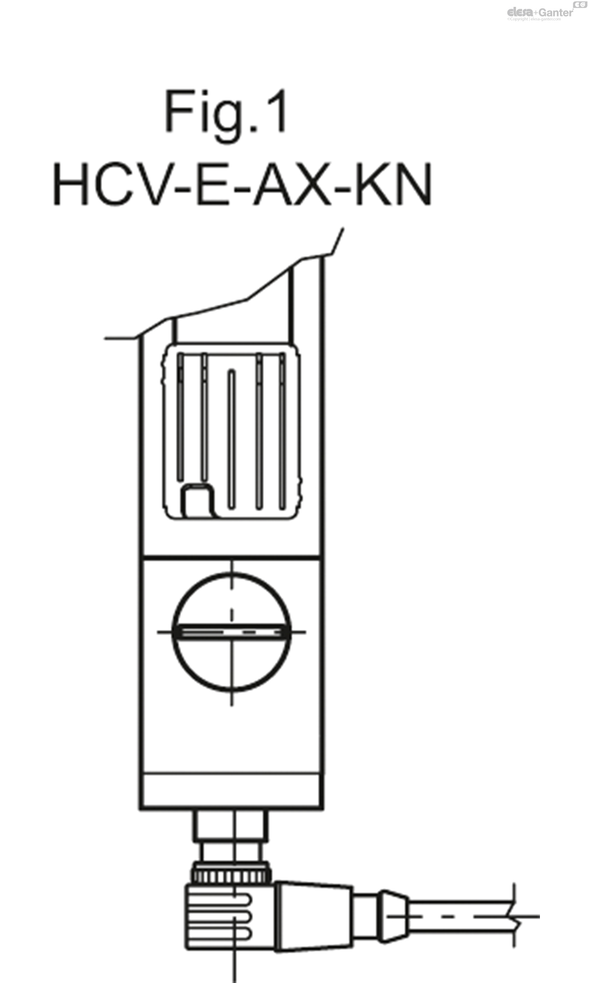
In case of use of an extension with angled connector, the direction of the cable output is shown in Fig.1.
Technical data
In laboratory tests carried out with mineral oil type CB68 (according to ISO 3498) at 23°C for a limited period of time, the weld stood up to: 18 bar (HCV.76), 18 bar (HCV.127) and 12 bar (HCV.254).
For use with fluids other than mineral oils and under particular different pressure and temperature conditions, please contact ELESA Technical Department.
In any case we suggest to verify the suitability of the product under the actual working conditions.
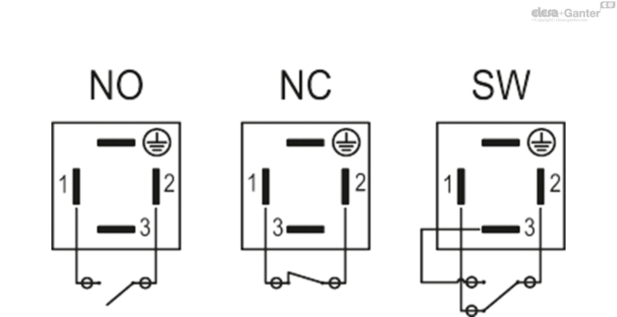
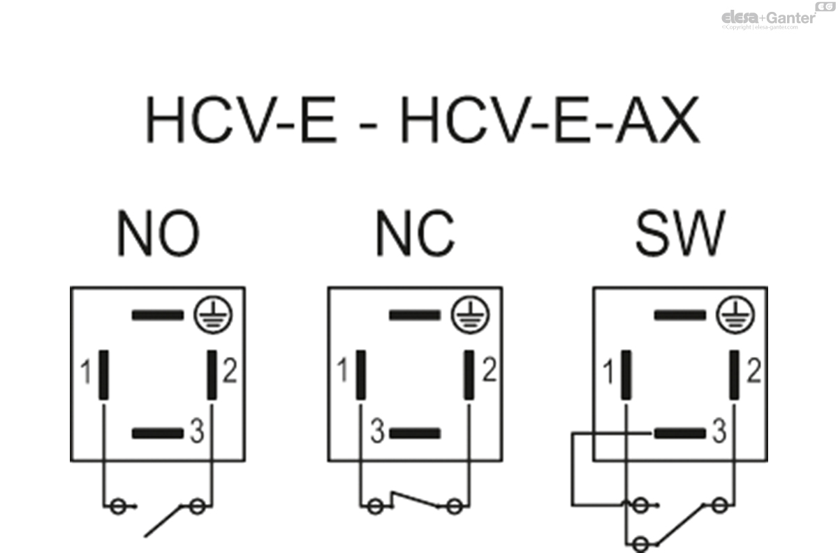
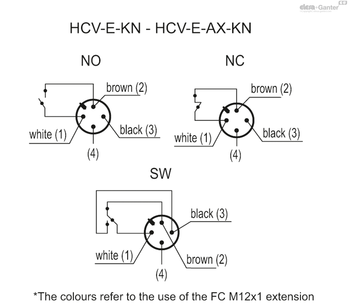
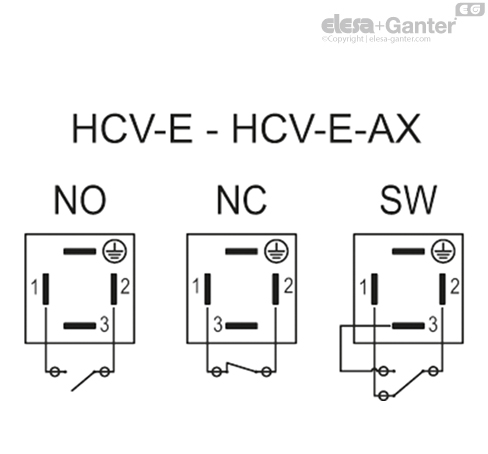
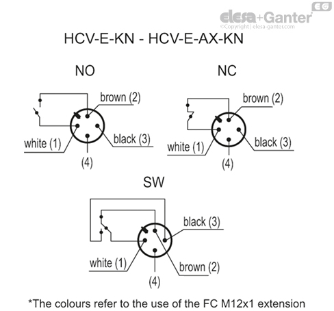
Functioning of the sensors
- NO: the electrical contact closes on reaching the minimum level.
- NC: the electrical contact is opened when it reaches the minimum level.
- SW (change-over electrical contact): the electrical contact switches between the two terminals.
| Electrical features | MIN level sensor | |
|---|---|---|
| Power supply | AC/DC | |
| Electric contacts | NO normally open NC normally closed SW change-over contact | |
| Maximum applicable voltage | NO: 140 Vac, 200 Vdc | DIN 43650 C |
| NC: 140 Vac, 150 Vdc | ||
| SW: 140 Vac, 150 Vdc | ||
| 30 Vac, 30Vdc | KN | |
| Voltage range (Type KN) | <30 Vac, <30Vdc | |
| Maximum switching current | 1 A | |
| Maximum current | NO: 1.2A NC: 2A SW: 2A | |
| Maximum commutable power | NO: 10 Va NC: 20 Va SW: 20 Va | |
| Cable gland (only HCV-E - HCV-E-AX) | Pg 7 (for cables in sheath with Ø 6 or 7 mm) | |
| Conductors cross-section (only HCV-E - HCV-E-AX) | Max. 1.5 mm2 | |
| Connector (only HCV-E-KN - HCV-E-AX) | M12x1 | |
| Do not mount this indicator in proximity to magnetic fields. | ||
Special executions on request
- Level indicators with stainless steel screws, nuts and washers.
- Level indicators HCV.76 with screws M12.
- Level indicators for use with fluids containing alcohol.
- UV resistant transparent technopolymer level indicators.
Accessories on request
FC.M12x1: extensions with 4 pole M12 female axial connector.
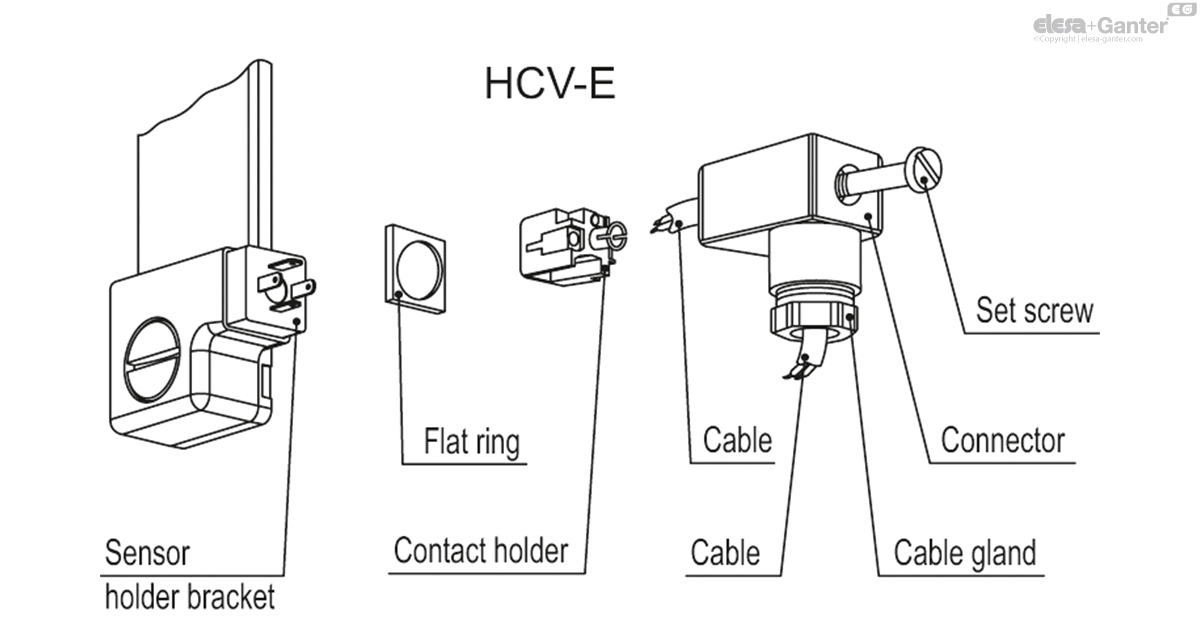
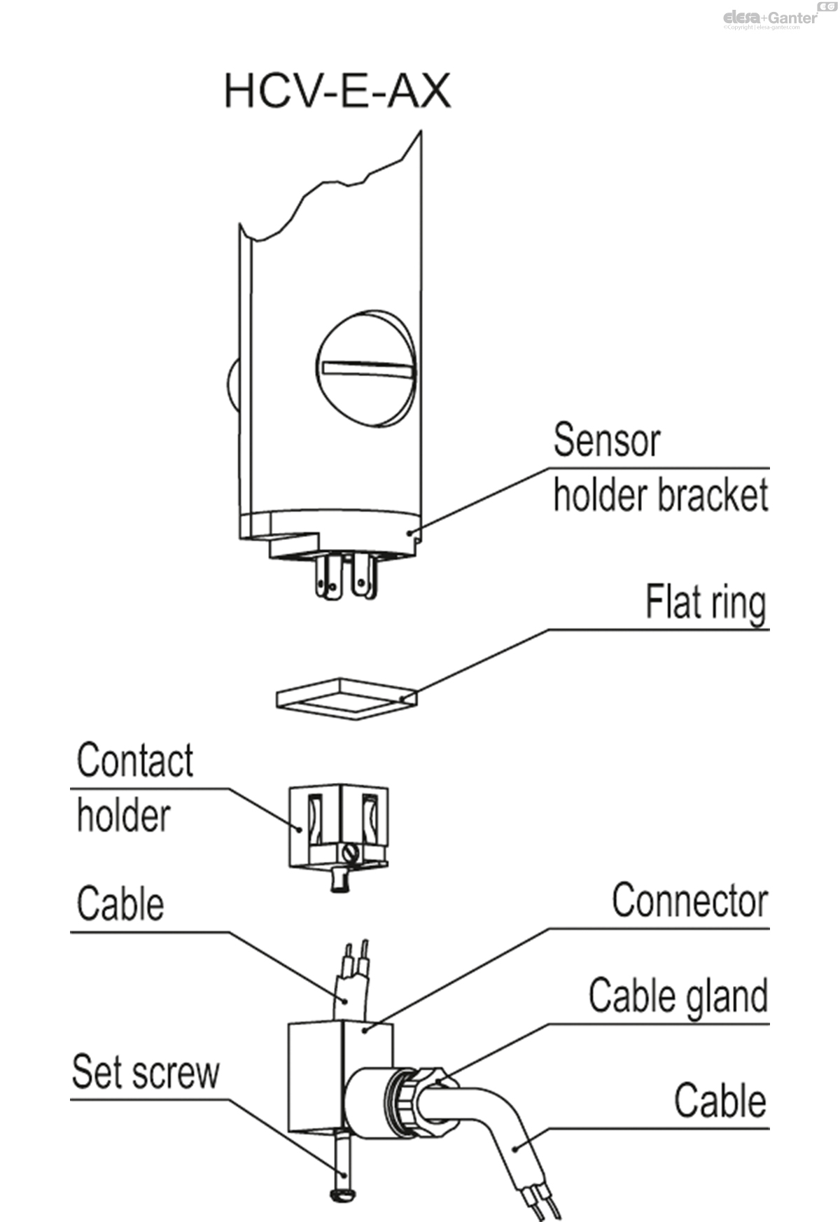
Female connector assembly instructions
- Remove the connector from the indicator by unscrewing the set screw placed on the connector, take the contact holders out and loosen the cable gland.
- Slip on the cable into the connector (standard connector) and connect the wires to the terminals 1 and 2 (NO and NC version) or 1,2 and 3 (SW version) of the contact holder.
- Assemble by pressing the contact holder into the connector in the required position.
- Screw the connectors to the indicator and then tighten the cable glands.
Gerelateerde producten

HCK-E
Elektrische niveau-indicatoren
met elektrische sensor voor niveau MIN
HCK-E-S
Elektrische niveau-indicatoren
met MIN niveau elektrische sensor, temperatuursensor of sonde
HCK-S
Elektrische niveau-indicatoren
met temperatuursensor of -sonde
NEW
HCV-E-NO-LD
Elektrische niveau-indicatoren met LED
met MIN niveau elektrische sensor, transparant technopolymeer
HCV-E-S
Elektrische niveau-indicatoren
met MIN niveau elektrische sensor, temperatuursensor en sonde, transparant technopolymeer
HCV-S
Elektrische niveau-indicatoren
met temperatuursensor en sonde, transparant technopolymeer
HCY-E
Elektrische oliepeilglazen
met MIN-niveausensor, technopolymeer
HCY-E-ST
Elektrische oliepeilglazen
met MIN-niveau- en MAX-temperatuursensoren, technopolymeer