

 Technical datasheet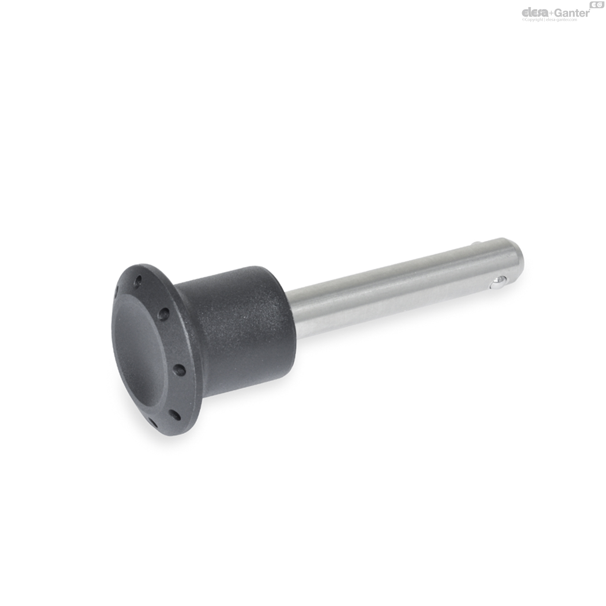
GN 124.2Stainless Steel-Locking pins
Stainless Steel-Locking pins
with axial lock (Ball retainer)
GN 124.2
|
Catalogue
|
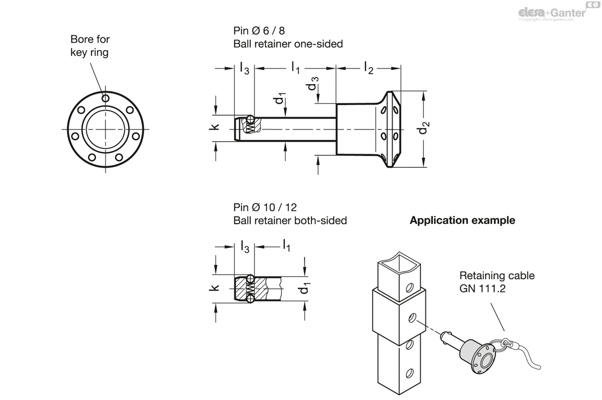
d1 -0.04/-0.08
|
l1
|
d2
|
d3
|
k
|
l2
|
l3
|
Location bore
|
Axial holding
force in N ≈ |
Load in kN ≈
Load capacity in kN ≈ Double sided shearing resistance according DIN 50141 (breaking strength) |

|
|
|---|---|---|---|---|---|---|---|---|---|---|---|---|
|
6
|
10
|
26
|
17.5
|
6.5
|
22
|
5
|
6
|
8
|
22
|
14
| ||
|
6
|
15
|
26
|
17.5
|
6.5
|
22
|
5
|
6
|
8
|
22
|
15
| ||
|
6
|
20
|
26
|
17.5
|
6.5
|
22
|
5
|
6
|
8
|
22
|
16
| ||
|
6
|
25
|
26
|
17.5
|
6.5
|
22
|
5
|
6
|
8
|
22
|
17
| ||
|
6
|
30
|
26
|
17.5
|
6.5
|
22
|
5
|
6
|
8
|
22
|
19
| ||
|
6
|
50
|
26
|
17.5
|
6.5
|
22
|
5
|
6
|
8
|
22
|
16
| ||
|
8
|
15
|
26
|
17.5
|
8.7
|
22
|
6.3
|
8
|
15
|
40
|
17
| ||
|
8
|
20
|
26
|
17.5
|
8.7
|
22
|
6.3
|
8
|
15
|
40
|
16
| ||
|
8
|
25
|
26
|
17.5
|
8.7
|
22
|
6.3
|
8
|
15
|
40
|
20
| ||
|
8
|
30
|
26
|
17.5
|
8.7
|
22
|
6.3
|
8
|
15
|
40
|
26
| ||
|
8
|
50
|
26
|
17.5
|
8.7
|
22
|
6.3
|
8
|
15
|
40
|
34
| ||
|
10
|
15
|
34
|
23
|
12
|
28.5
|
8.7
|
10
|
30
|
62
|
40
| ||
|
10
|
20
|
34
|
23
|
12
|
28.5
|
8.7
|
10
|
30
|
62
|
42
| ||
|
10
|
25
|
34
|
23
|
12
|
28.5
|
8.7
|
10
|
30
|
62
|
46
| ||
|
10
|
30
|
34
|
23
|
12
|
28.5
|
8.7
|
10
|
30
|
62
|
49
| ||
|
10
|
50
|
34
|
23
|
12
|
28.5
|
8.7
|
10
|
30
|
62
|
59
| ||
|
12
|
20
|
34
|
23
|
14.5
|
28.5
|
9.5
|
12
|
32
|
90
|
51
| ||
|
12
|
30
|
34
|
23
|
14.5
|
28.5
|
9.5
|
12
|
32
|
90
|
59
| ||
|
12
|
40
|
34
|
23
|
14.5
|
28.5
|
9.5
|
12
|
32
|
90
|
68
| ||
|
12
|
50
|
34
|
23
|
14.5
|
28.5
|
9.5
|
12
|
32
|
90
|
75
|
Pin
Stainless Steel AISI 303
Knob
Plastic Technopolymer (Polyamide PA)
- black-grey
- temperature resistant up to 80 °C
Ball
Stainless Steel AISI 420C
Spring
Stainless Steel AISI 631
GN 124.2 Stainless Steel-Locking pins are used for quick fixing, connecting and locking of various jig and fixture systems.
The locking balls are held in position by a pressure spring and are therefore not rigidly locked. The bolts can be quickly and easily inserted and removed from the locating hole.
The rated shear stresses of the bolt cross-section are theoretical guide values only and do not constitute any warranty. They constitute no general warranty of quality and condition. The user must determine from case to case whether a product is suitable for the intended use.
This standard replaces the previous Stainless Steel-Locking pins GN 124.