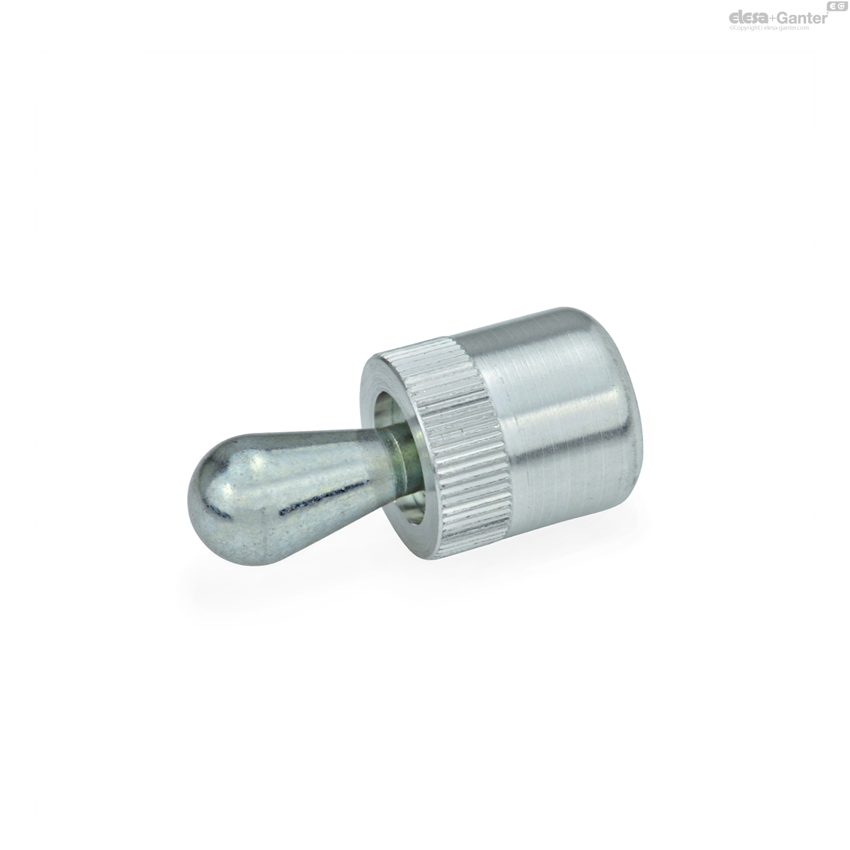
715-10-205-SA GN 715-SA Thrust pin steel, without seal

Expected delivery time 5-7 working days
Prices, live stock & CAD downloads
Sign in to see your prices and stock, download CAD files and order directly online.
Sign in Request an account Technical datasheet
Technical data
- Catalogue
- GN 715-10-205-SA
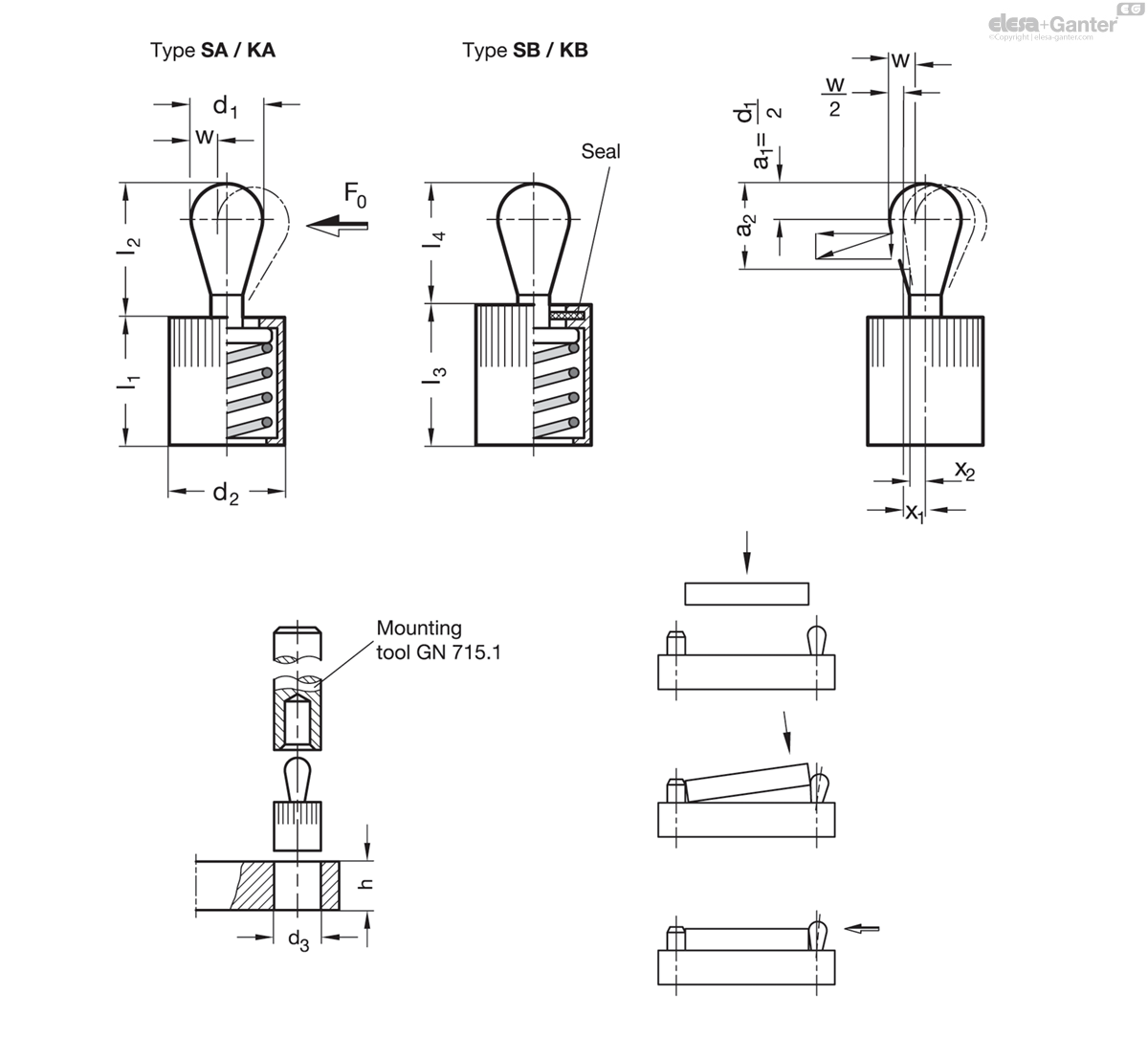
- d1
- 10
- Side thrust force
F in N - 205
- d2
- 16
- l1 -1
- 18
- l2 ±0.5
- 16.7
- l3 ±0.5
- 11.7
- w
- 1.6
- Code no. for
mounting tool - GN 715.1-10

- 16
Types
Types
- Type SA: Thrust pin steel, without seal
- Type KA: Thrust pin plastic, without seal
- Type SB: Thrust pin steel, with seal
- Type KB: Thrust pin plastic, with seal
Housing
Housing
Aluminum
Plain
Thrust pin
Thrust pin
- Steel for type SA / SB
- Hardened
- Zinc plated, blue passivated
- Plastic for type KA / KB
- Polyacetal (POM)
Thrust spring
Thrust spring
- Side thrust force light
- Stainless steel AISI 301
- Side thrust force medium
- Spring steel blackened
- Side thrust force heavy
- Spring steel zinc plated, blue passivated
Seal
Seal
Chloroprene rubber (CR)
Spring loaded side thrust pins GN 715 are versatile and practical elements for holding, positioning and clamping of workpieces.
They eliminate costly alternatives, are space saving and easy to install. The knurled body requires only a hole tolerance of H8.
For mounting the side thrust pins a suitable mounting tool GN 715.1 is available (see table).
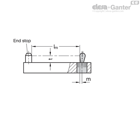
The position of the mounting hole results from the workpiece length lm plus the hole offset m, which is calculated as shown below:
w = Maximum movement range of the thrust pin
t = Workpiece height
m = Hole offset
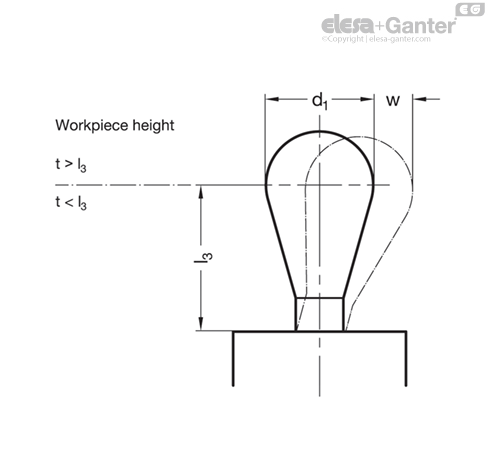
Case 1:
The workpiece height t is greater than the cone height l3
m = d1/2 - w/2
Case 2:
The workpiece height t is smaller than the cone height l3
m = d1/2 - (l3-t) x 0,123
If the position of the mounting hole is determined as specified, the full movement of the side thrust pin will be available to cover the tolerance of the workpiece.
In case 1, the lateral clamping force is coupled with a downward pull that presses the workpiece against the contact surface.
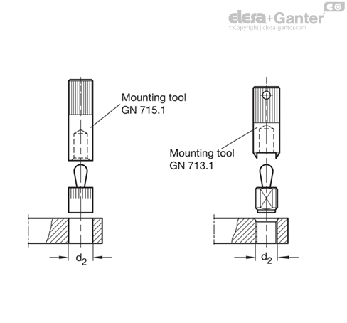
The use of a mounting tool GN 715.1 or mounting tool GN 713.1 is recommended for installation.
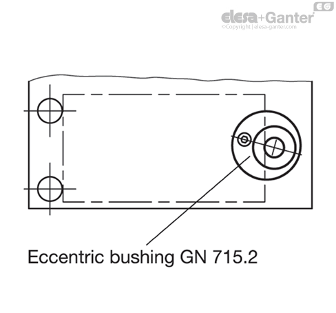
Eccentric bushings GN 715.2 are an assembly aid for side thrust pins GN 714 / GN 715. They enable adjustment of the side thrust pins to the most favorable clamping position, e.g. to bridge larger tolerance ranges of a workpiece.