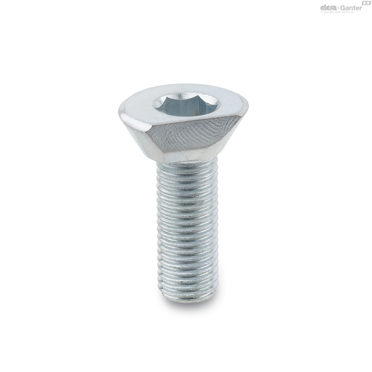
418.2-12-M5-10-R
GN 418.2 Spiraalspanschroeven

Lt: 1-2 weken Alle maten en varianten van GN 418.2
🔒 Prijzen, actuele voorraad & CAD-downloads
Meld u aan om uw prijzen en voorraad te zien, CAD-bestanden te downloaden en direct online te bestellen.
Aanmelden Account aanvragen Technische fiche
Technische gegevens
- Code
- GN 418.2-12-M5-10-R
- d1 Nominal dimension
- 12
- d1
- 11.7
- d2
- M 5
- l
- 10
- h1
- 4
- h2
- 3.5
- r1
- 5
- r2
- 5.7
- s1
- 1.16
- s2
- 0.7
- A/F
- 3
- x ±0.2
- 4.2
- z ±0.2
- 5.2
- Max. tightening torque
in Nm - 2
- Max. clamping
force F in kN - 0.1

- 3
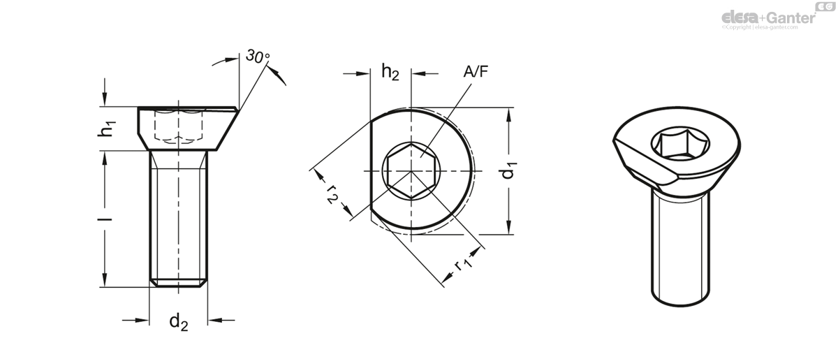
Type
Type R: Clamping by clockwise rotation
(d2 = right-hand thread)
Steel
- case hardened HRC 56 ±1
- Tensile strength class 8.8
- zinc plated, blue passivated
Cam point screws GN 418.2 are sturdy and compact elements, requiring a minimum of installation space and offering ultimate convenience and ease in handling.
The clamping forces F given in the table refer to the maximum permitted tightening torque and the specified screw-in depth t.
Function
The head of the cam point screw has two cams: a radial clamping cam (with additional 30° taper) and an axial draw-down cam. The cam ensures that the clamping force is the same in any angular position. The cam is also self-locking.
Force components act on the clamping point which generate a draw-down effect and which, in addition to the friction, cause the workpiece to be pressed against a fixed stop. An additional draw-down effect is created by the thread and the 30° taper.
To ensure safe and secure clamping in every application, a right-hand version (with right-hand thread) and a left-hand version (with left-hand thread) is available.

Assembly instructions
- Position the thread bore(s) as specified
- Screw the cam point screw in to the desired height and place it with its flat side facing the workpiece (note the minimum screw-in depth t)
- For clamping effect above the head taper, the minimum clamping height should be h2
- A turn of approx. 135° is required for clamping

