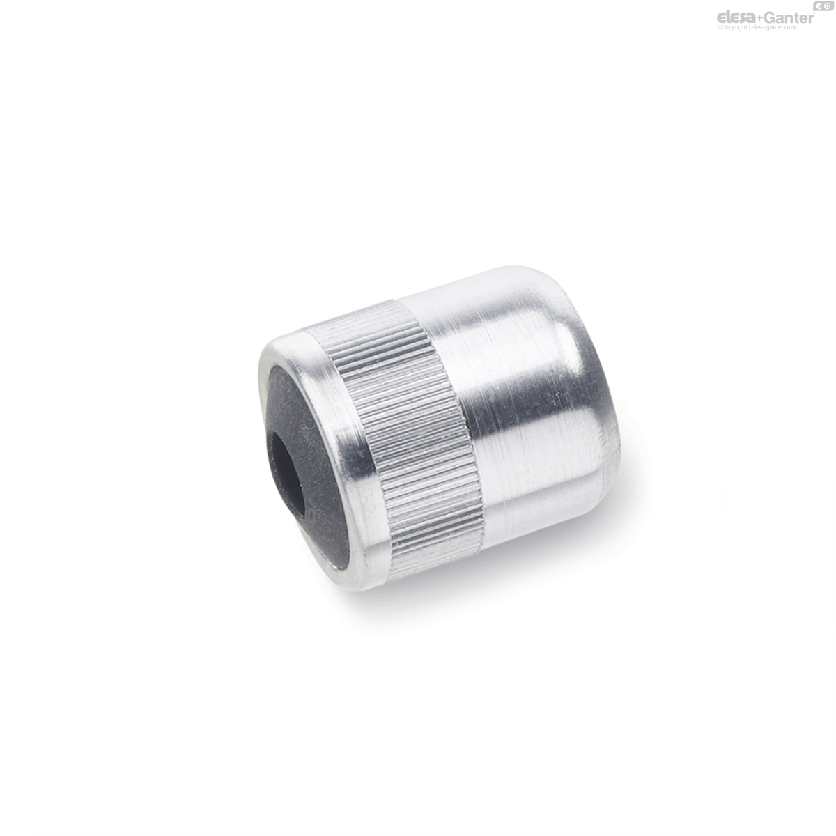
714-10-75 GN 714 Zij-aandrukstukken

Verwachte levertermijn 5-7 werkdagen
Prijzen, actuele voorraad & CAD-downloads
Meld u aan om uw prijzen en voorraad te zien, CAD-bestanden te downloaden en direct online te bestellen.
Aanmelden Account aanvragen Technische fiche
Technische gegevens
- Code
- GN 714-10-75
- d1
- 10
- Side thrust
F0 in N ≈
at l2 - 75
- d2
- M 4
- d3 H8
- 10
- h min.
- 12
- l1 -1
- 12
- l2
- 7.5
- l3
- 1.5
- l4
- 4.5
- w
- 2
- Code no.
- GN 715.1-5.6

- 2
Housing Aluminium
blank
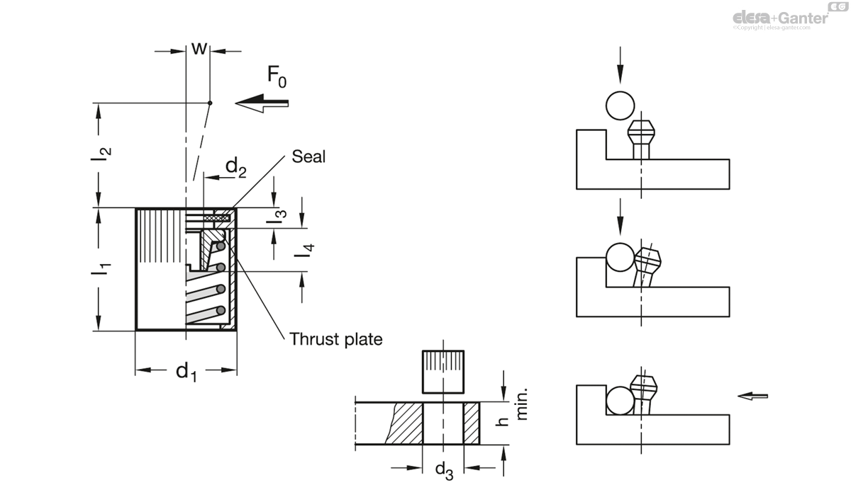
Thrust plate with female thread
hardened, blackened
Thrust spring coding
Force, low thrust: grey
medium thrust: lack
high thrust: silver
Seal rubber
NBR (Perbunan)
Side thrust pins GN 714 are the result of further development of GN 715 It is left to the customer to design his own pressure pin which can be screwed into the thrust plate.
This design extends the field of applications for side thrust pins offering identical advantages i.e. they eliminate costly alternatives, are space saving and are simple to install. The knurled body requires bore to H8 tolerance only.
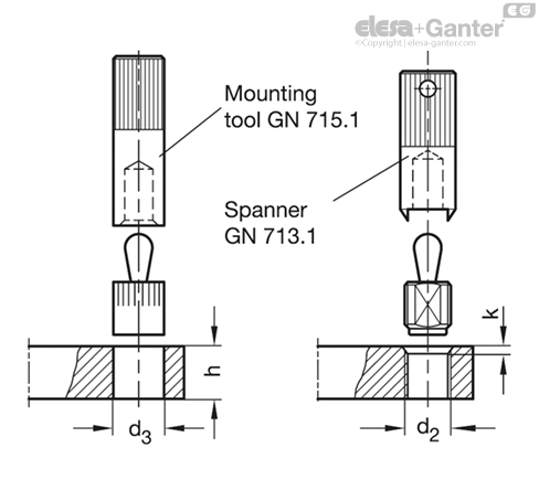
For easy mounting a suitable tool GN 715.1 is available (see table).
- Mounting tools GN 715.1 (Code no. see table)
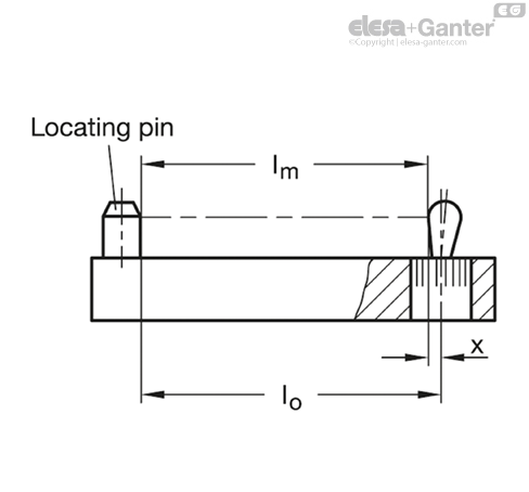
w = Movement of pin
F = Side thrust in N
initial thrust = F0
end thrust = 1.1 x F0
a2-a1 = Clamping range for workpiece
x = distance centre line – thrust point at w2
x1 for highest thrust point (a1)
x2 for lowest thrust point (a2)
l0 = Distance end stop – bore of thrust bush
l0 = lm + x
lm = Average length of workpiece lmax. + lmin./2
For contact points (workpiece height) between a1 and
a2 a value for x has to be used lying between x1 and
x2 (interpolation).
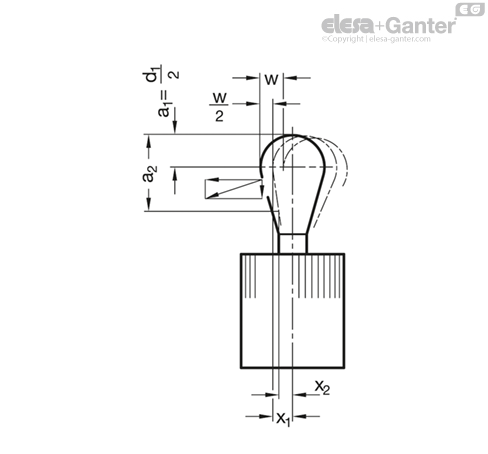
By observing the above values the full movement of the side thrust pin will be available to cover the tolerance of the workpiece.
For inserting the side thrust pins the use of a mounting tool GN 715.1 or spanner GN 713.1 is recommended.
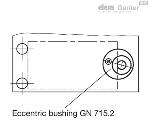
Eccentric bushes GN 715.2 are tooling accessory for GN 714 /GN 715. They enable a precise optimum setting of side thrust pins. This allows an adjustment to l0 to accommodate for instance a larger tolerance range on a workpiece.