 Technical datasheet
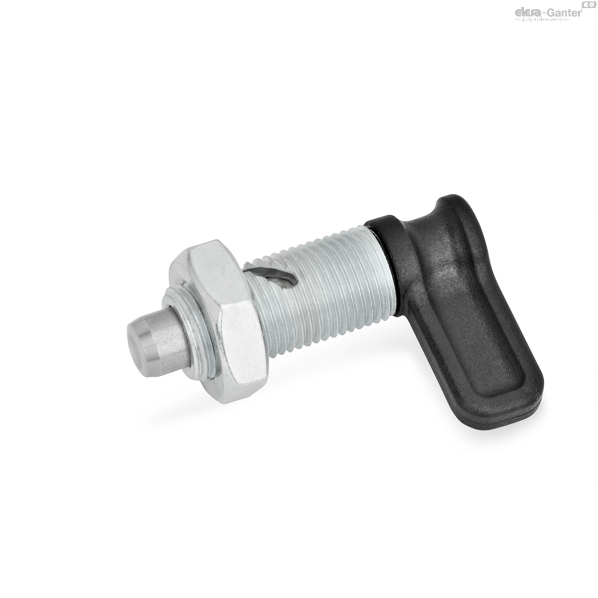
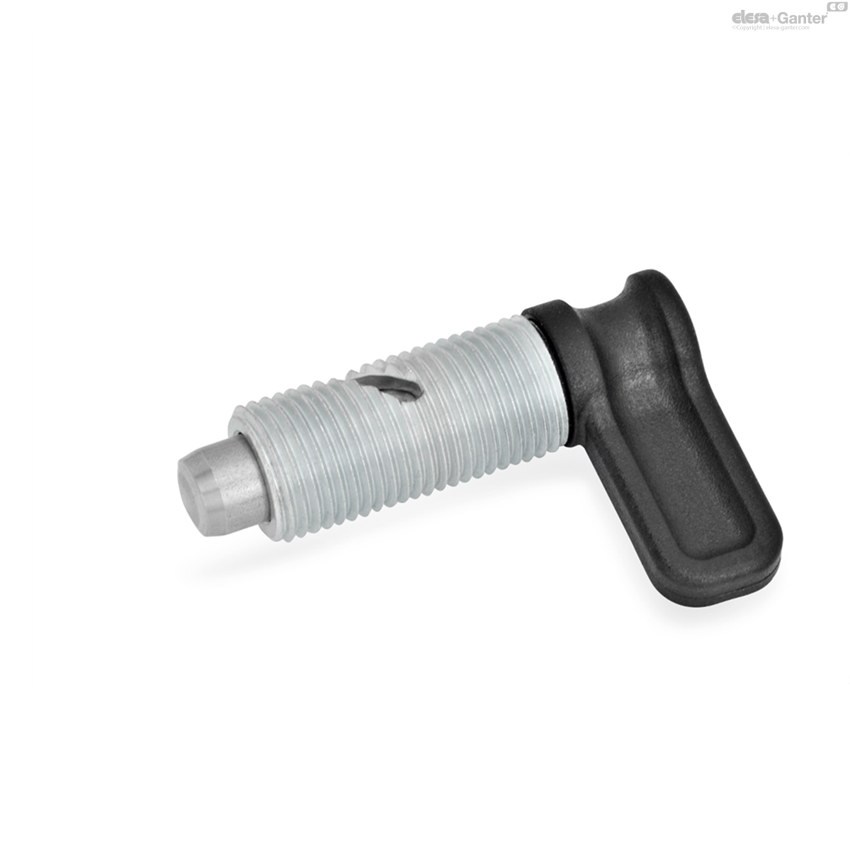
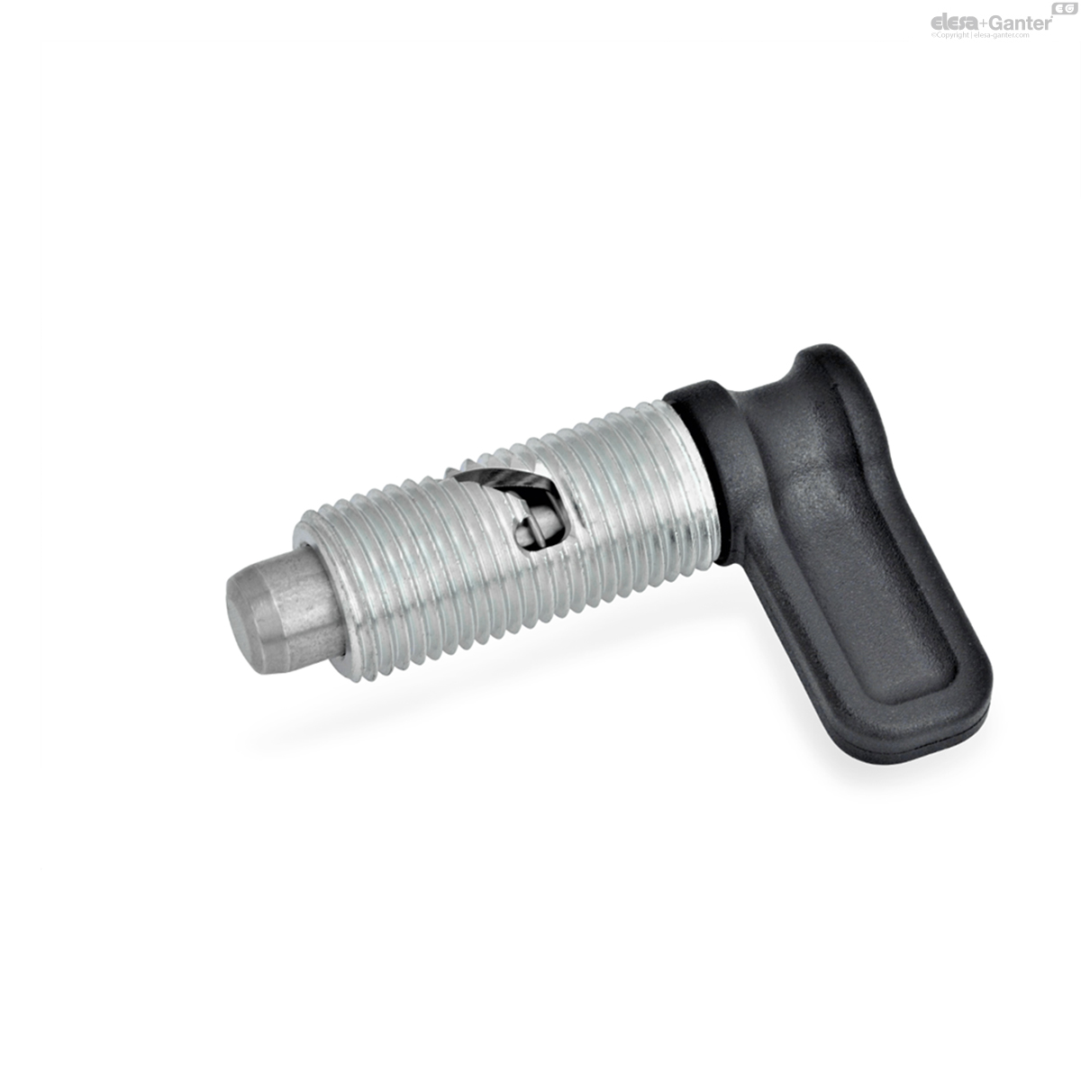
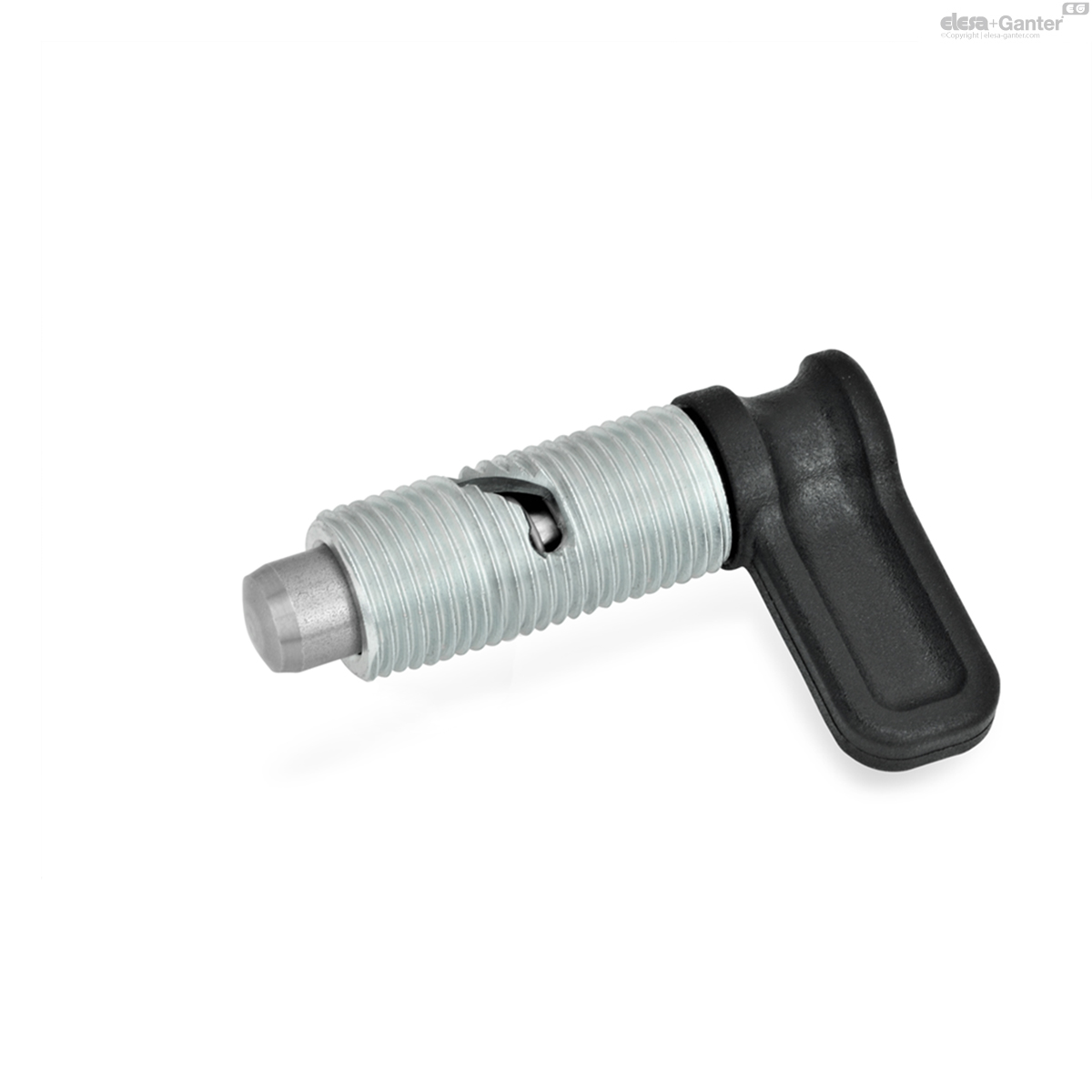
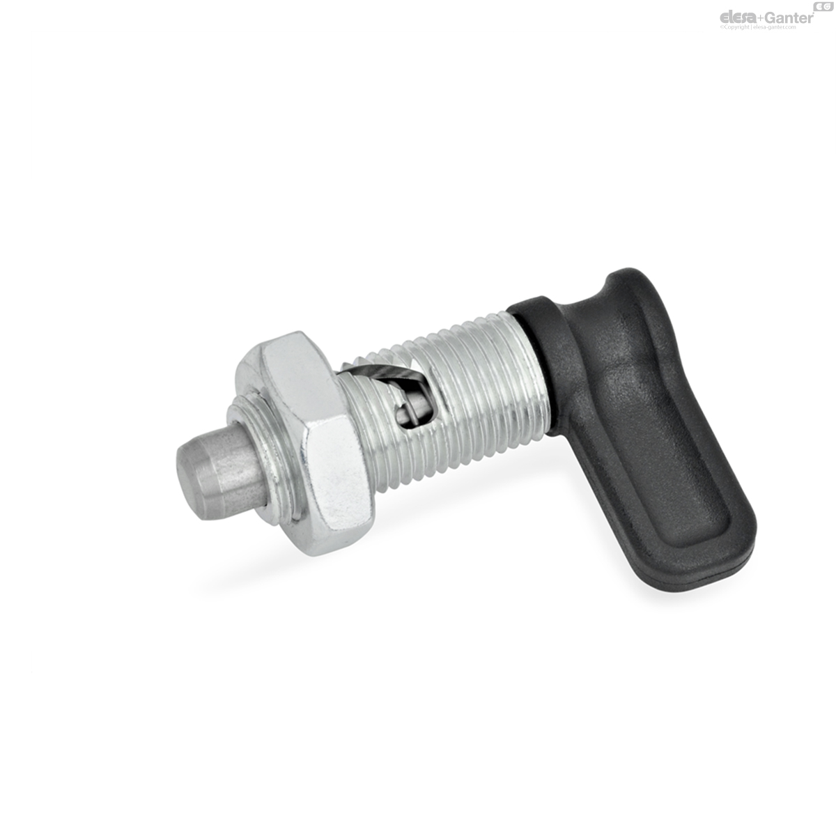
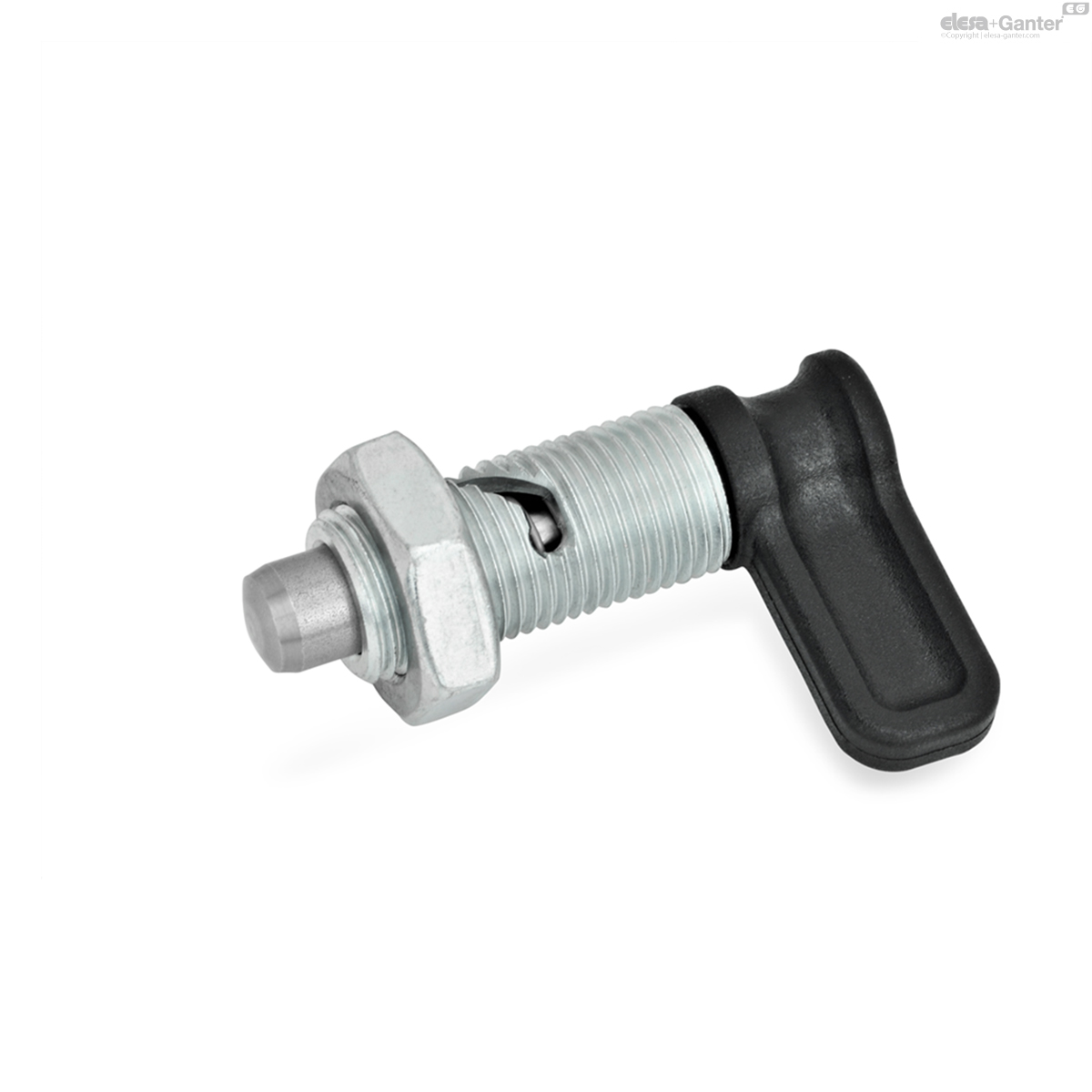
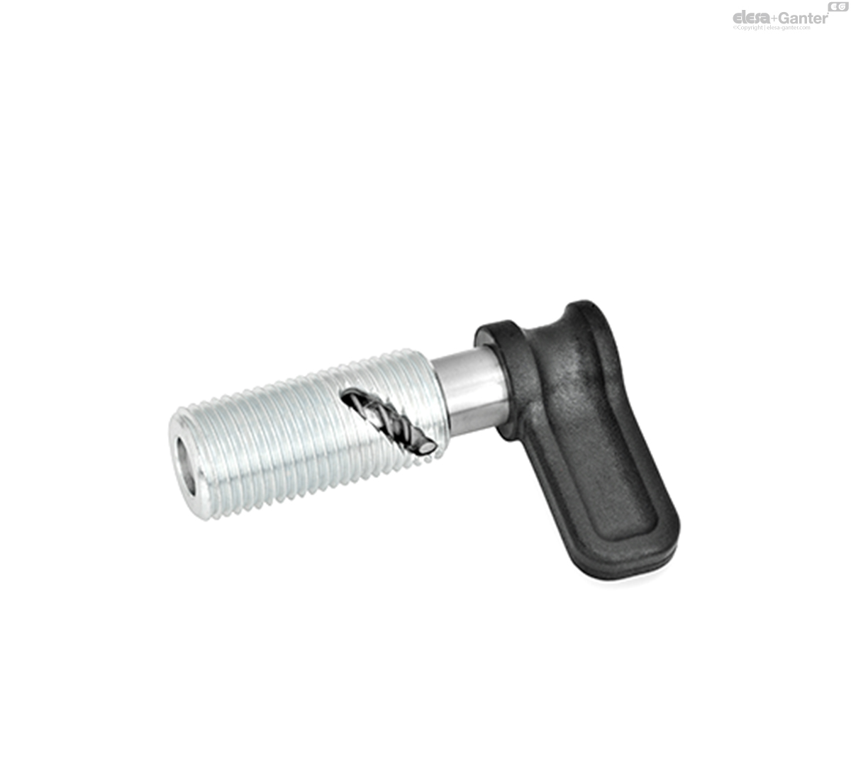
GN 712-AKDoigts d'indexage à came
Sans position de repos, avec contre-écrou
Acier, loquet en plastique, tige de piston en position standard (saillante)

GN 712-AK
|
Code
|
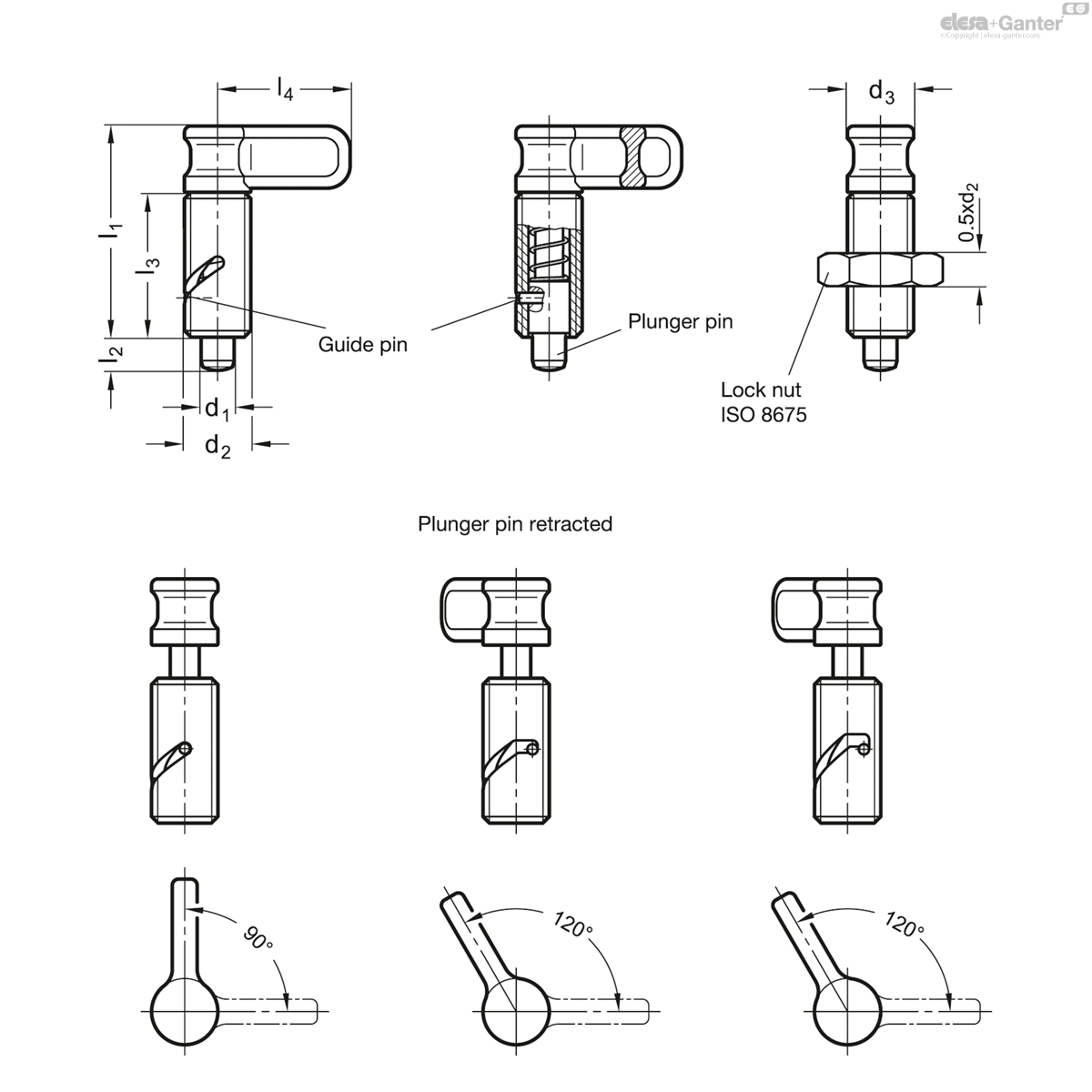
d1 Pin h9 Bore +0.03/+0.1
|
d2
|
d3
|
l1 ≈
|
l2
|
l3 min.
|
l4
|
Spring load
in N≈ initial |
Spring load
in N≈ end |
|
|---|---|---|---|---|---|---|---|---|---|---|
|
|
|
|
|
|
|
|
|
|
|
|
|
GN 712-6-M16x1,5-AK
|
6
|
M 16 x 1.5
|
16
|
51
|
8
|
35
|
32
|
6.5
|
20
|
68
|
|
GN 712-8-M16x1,5-AK
|
8
|
M 16 x 1.5
|
16
|
51
|
8
|
35
|
32
|
6.5
|
20
|
69
|
|
GN 712-10-M16x1,5-AK
|
10
|
M 16 x 1.5
|
16
|
51
|
8
|
35
|
32
|
6.5
|
20
|
71
|
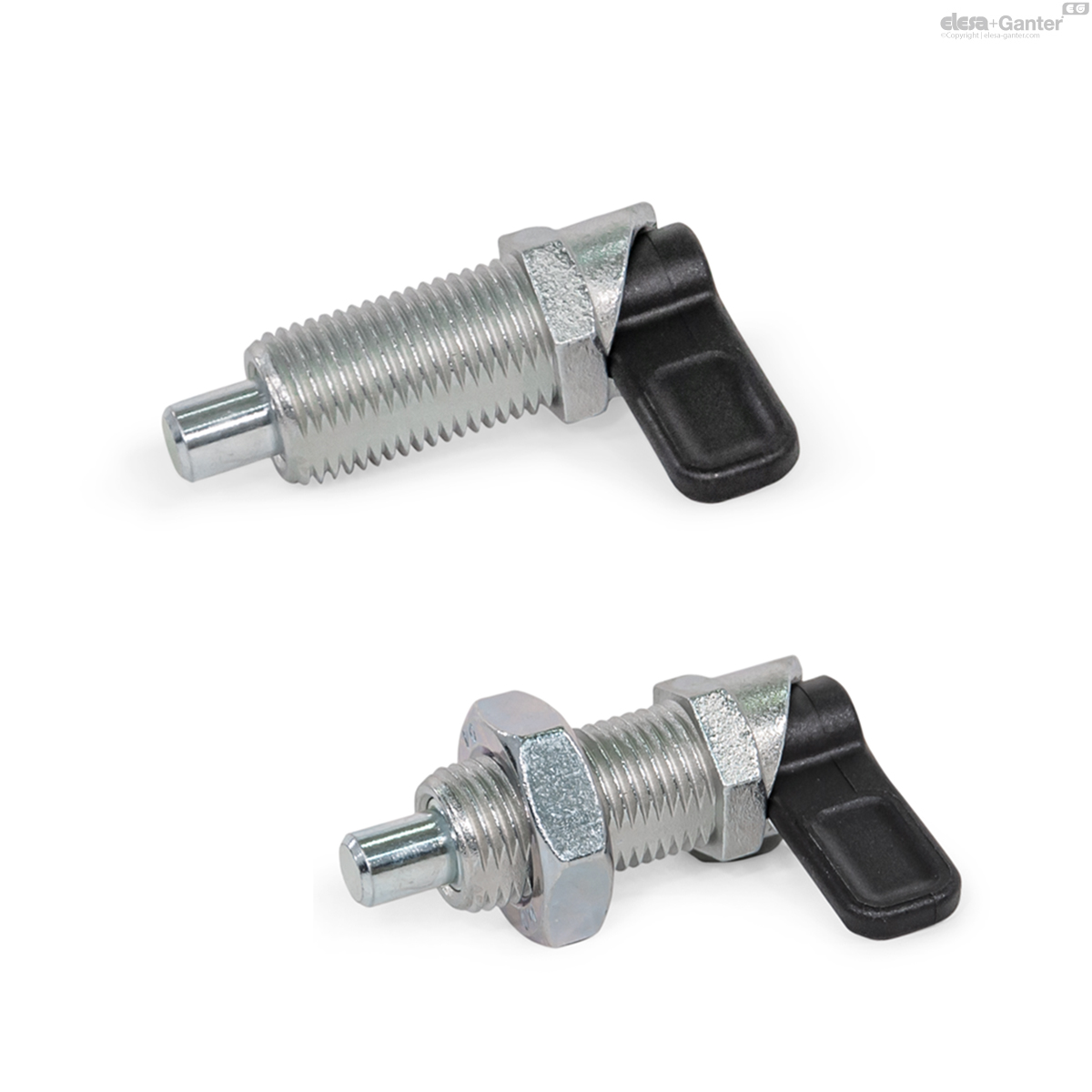
Types
- Type A: Without rest position, without lock nut
- Type AK: Without rest position, with lock nut
- Type R: With rest position, without lock nut
- Type RK: With rest position, with lock nut
- Type S: With safety-rest position, without lock nut
- Type SK: With safety-rest position, with lock nut
Guide
Steel zinc plated, blue passivated
Plunger pin
Stainless steel AISI 303
Latch
Plastic, Polyamide (PA)
- Black, matte finish
- Not removable
Cam action indexing plungers GN 712 are used in such applications where the plunger pin must not protrude continually.When turning the cam by 90° resp. 120° degrees in anti-clockwise direction, the plunger pin is retracted through a curved opening in the body.
Depending on the type, the plunger pin is moved back by a pressure spring in its original position (Type A), is held in retracted position (Type R), resp. is secured against accidental operation (Type S). In order to move the plunger pin, this safety version requires an additional lifting of the latch.
- Guide in stainless steel
Produits associés

GN 412.1
Support pour doigt d'indexage
pour doigts d'indexation / doigts d'indexation à came
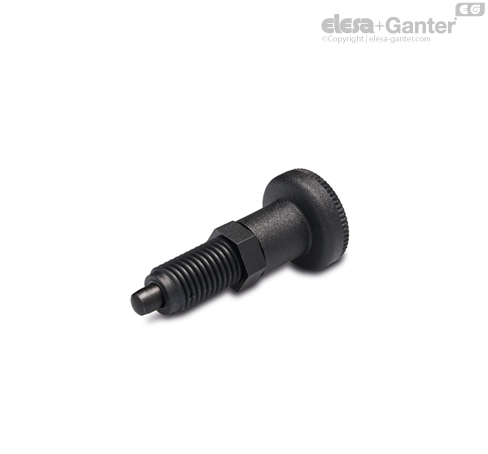
GN 612.8
Doigts d'indexage à came
Corps fileté en zinc moulé sous pression
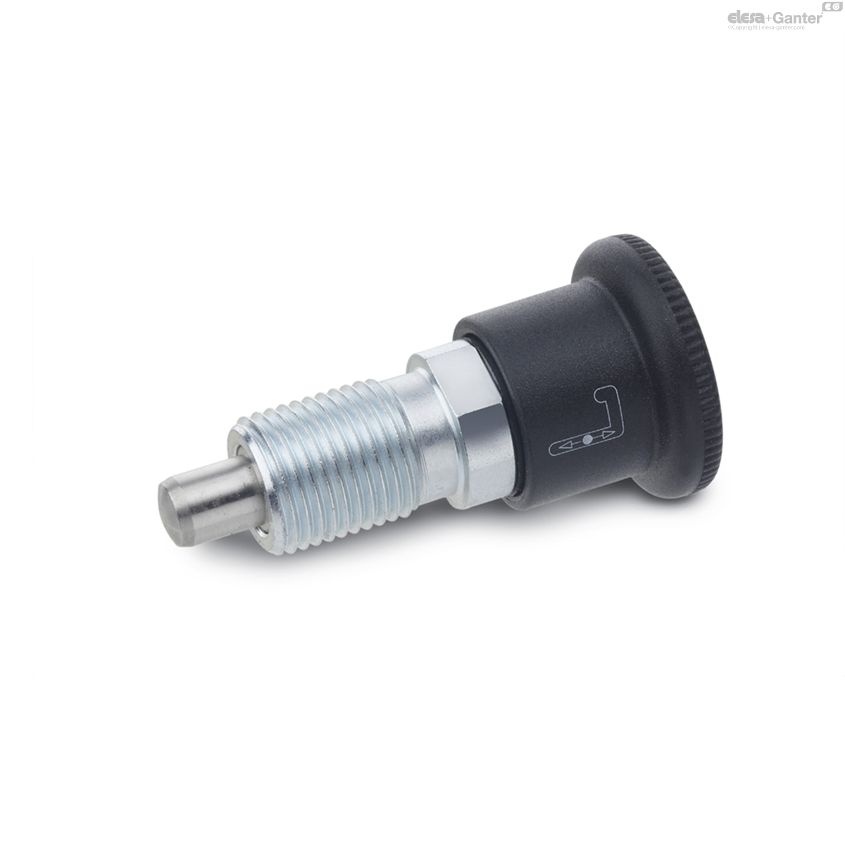
GN 712.1-A
Doigts d'indexage à came
Acier, loquet en plastique, tige de piston en position standard (rétractée)
GN 816
Doigts d'indexage à clé
La broche en position normale dépasse
PMT.100-A
Doigts d'indexation
Corps en SUPER-technopolymère

PMT.101-A
Doigts d'indexation
Position repos, Corps en SUPER-technopolymère

PMT.110-A
Doigts d'indexation
Corps en SUPER-technopolymère

PMT.200-A
Doigts d'indexation
Position repos, Corps en SUPER-technopolymère