 Technical datasheet
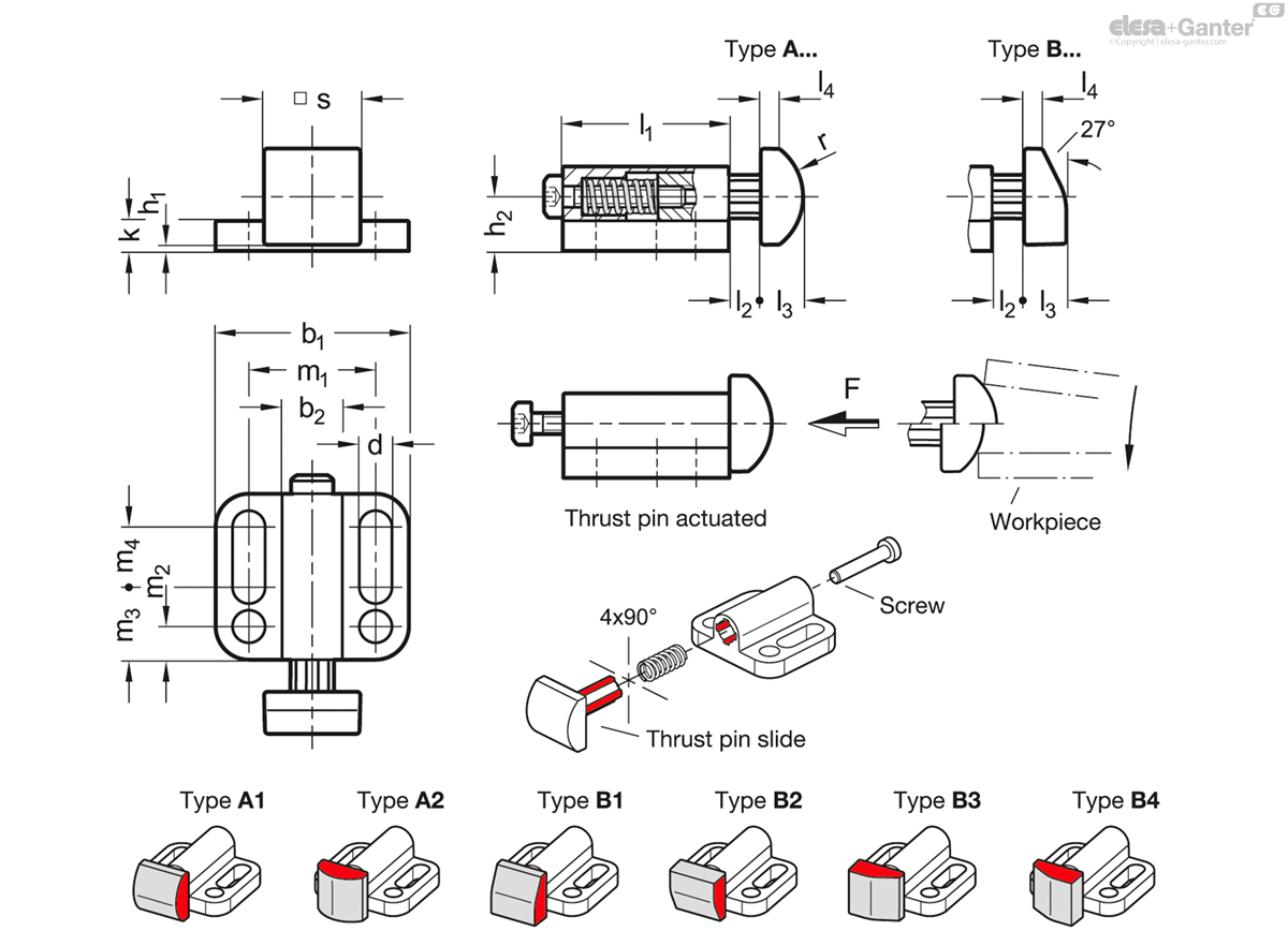
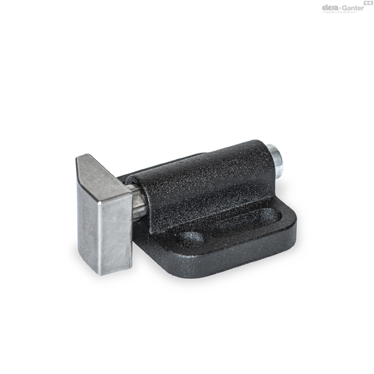
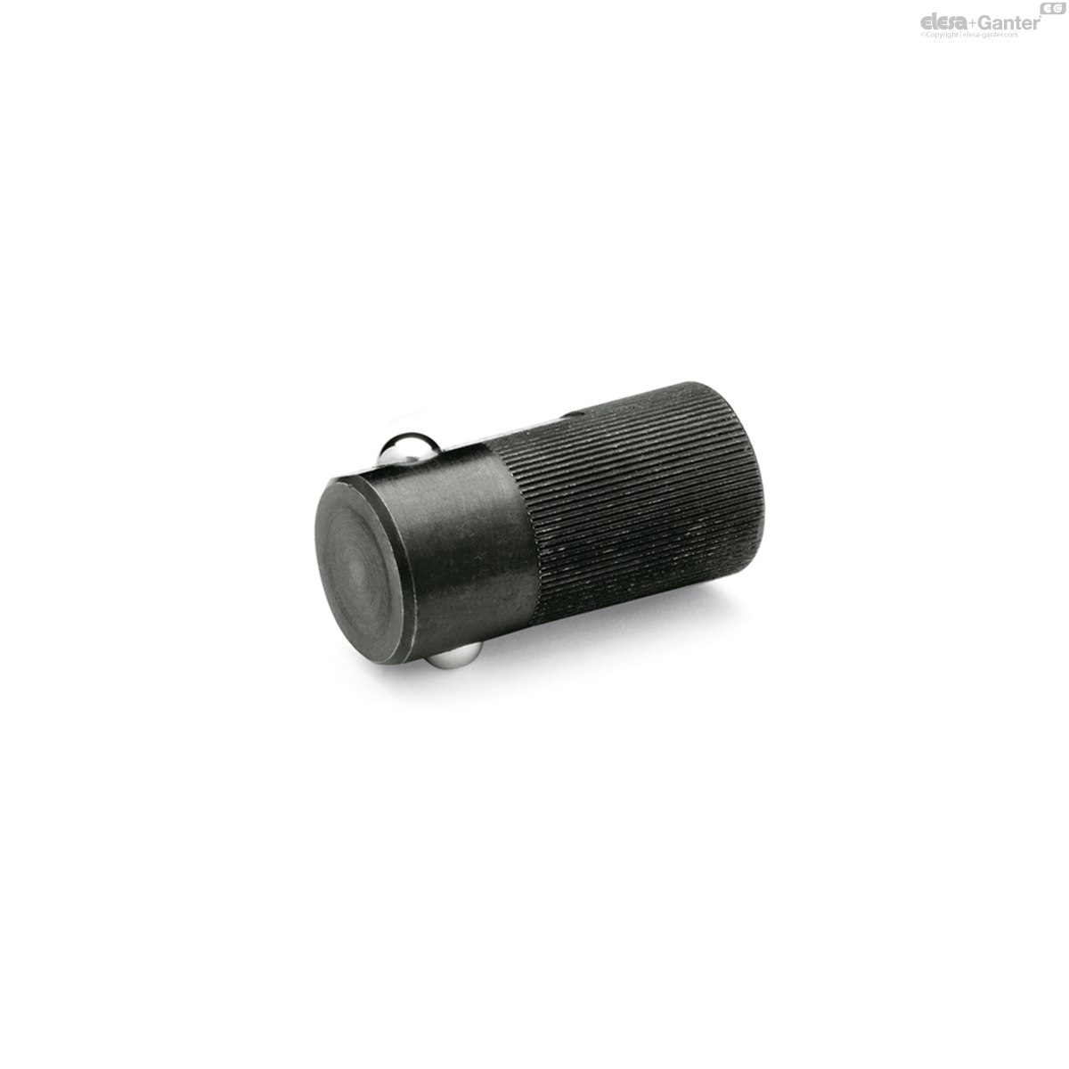
GN 415-A1Goupilles de poussée latérales
Cylindre, horizontal
GN 415-A1
|
Code
|
b1
|
b2
|
d
|
h1 +0.5
|
h2
|
k
|
l1
|
l2 ≈
|
l3
|
l4 ≈
|
m1
|
m2
|
|---|---|---|---|---|---|---|---|---|---|---|---|---|
|
|
|
|
|
|
|
|
|
|
|
|
|
|
|
GN 415-ZD-22-A1-KG-1
|
22
|
7
|
3.3
|
1
|
6
|
4
|
16.5
|
2.8
|
4.8
|
2.4
|
14
|
4
|
|
GN 415-ZD-22-A1-KG-2
|
22
|
7
|
3.3
|
1
|
6
|
4
|
16.5
|
2.8
|
4.8
|
2.4
|
14
|
4
|
|
GN 415-ZD-22-A1-NG-1
|
22
|
7
|
3.3
|
1
|
6
|
4
|
16.5
|
2.8
|
4.8
|
2.4
|
14
|
4
|
|
GN 415-ZD-22-A1-NG-2
|
22
|
7
|
3.3
|
1
|
6
|
4
|
16.5
|
2.8
|
4.8
|
2.4
|
14
|
4
|
|
GN 415-ZD-22-A1-NR-1
|
22
|
7
|
3.3
|
1
|
6
|
4
|
16.5
|
2.8
|
4.8
|
2.4
|
14
|
4
|
|
GN 415-ZD-22-A1-NR-2
|
22
|
7
|
3.3
|
1
|
6
|
4
|
16.5
|
2.8
|
4.8
|
2.4
|
14
|
4
|
|
GN 415-ZD-32-A1-KG-1
|
32
|
10
|
5.4
|
1
|
9
|
5
|
27.5
|
5
|
7
|
3.1
|
21
|
5.5
|
|
GN 415-ZD-32-A1-KG-2
|
32
|
10
|
5.4
|
1
|
9
|
5
|
27.5
|
5
|
7
|
3.1
|
21
|
5.5
|
|
GN 415-ZD-32-A1-NG-1
|
32
|
10
|
5.4
|
1
|
9
|
5
|
27.5
|
5
|
7
|
3.1
|
21
|
5.5
|
|
GN 415-ZD-32-A1-NG-2
|
32
|
10
|
5.4
|
1
|
9
|
5
|
27.5
|
5
|
7
|
3.1
|
21
|
5.5
|
|
GN 415-ZD-32-A1-NR-1
|
32
|
10
|
5.4
|
1
|
9
|
5
|
27.5
|
5
|
7
|
3.1
|
21
|
5.5
|
|
GN 415-ZD-32-A1-NR-2
|
32
|
10
|
5.4
|
1
|
9
|
5
|
27.5
|
5
|
7
|
3.1
|
21
|
5.5
|
|
GN 415-ZD-39-A1-KG-1
|
39
|
14.5
|
6.5
|
1
|
12
|
6
|
35
|
8.2
|
10
|
4.7
|
27
|
6.5
|
|
GN 415-ZD-39-A1-KG-2
|
39
|
14.5
|
6.5
|
1
|
12
|
6
|
35
|
8.2
|
10
|
4.7
|
27
|
6.5
|
|
GN 415-ZD-39-A1-NG-1
|
39
|
14.5
|
6.5
|
1
|
12
|
6
|
35
|
8.2
|
10
|
4.7
|
27
|
6.5
|
|
GN 415-ZD-39-A1-NG-2
|
39
|
14.5
|
6.5
|
1
|
12
|
6
|
35
|
8.2
|
10
|
4.7
|
27
|
6.5
|
|
GN 415-ZD-39-A1-NR-1
|
39
|
14.5
|
6.5
|
1
|
12
|
6
|
35
|
8.2
|
10
|
4.7
|
27
|
6.5
|
|
GN 415-ZD-39-A1-NR-2
|
39
|
14.5
|
6.5
|
1
|
12
|
6
|
35
|
8.2
|
10
|
4.7
|
27
|
6.5
|
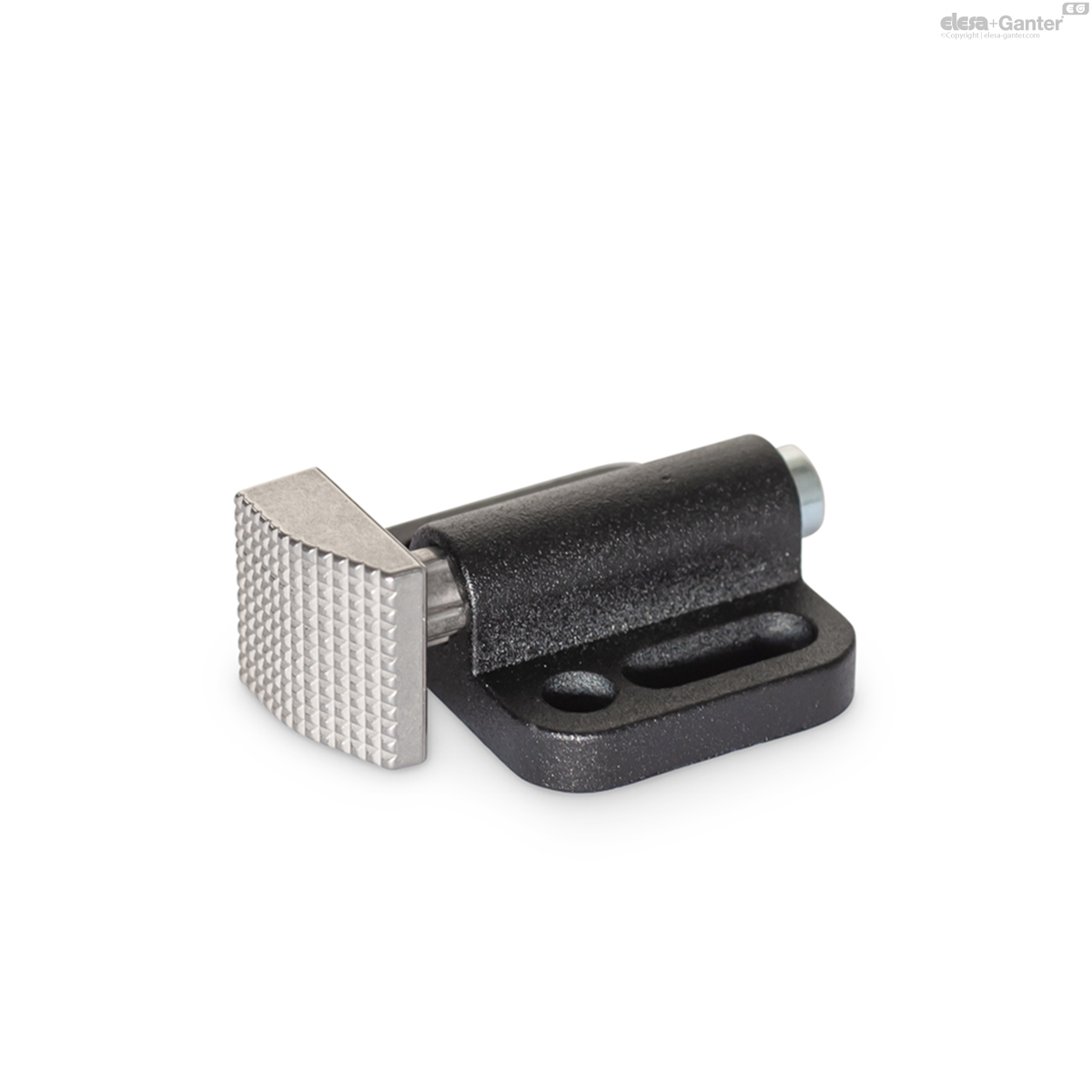
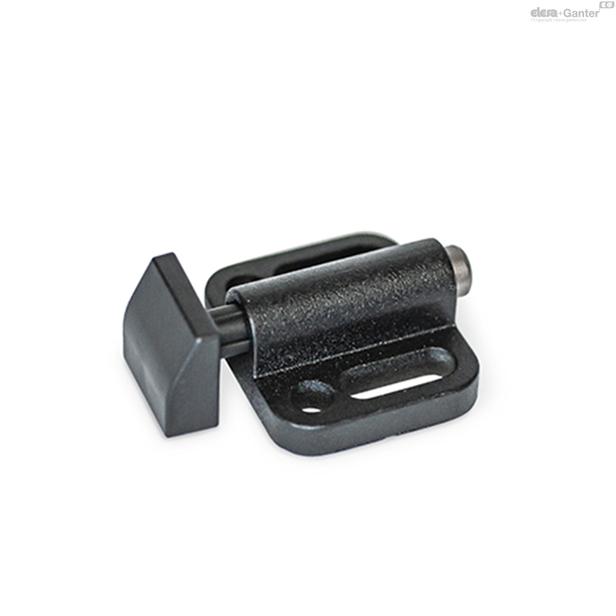
Types
- Type A1: Cylinder, horizontal
- Type A2: Cylinder, vertical
- Type B1: Wedge, top
- Type B2: Wedge, down
- Type B3: Wedge, right
- Type B4: Wedge, left
Identification no.
- No. 1: standard spring load
- No. 2: high spring load
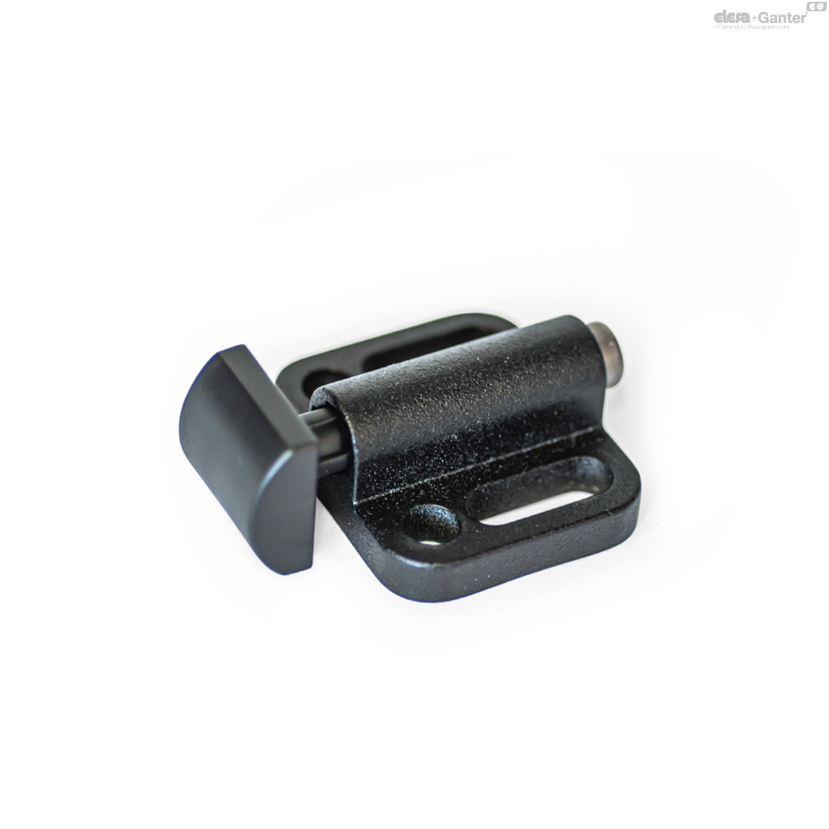
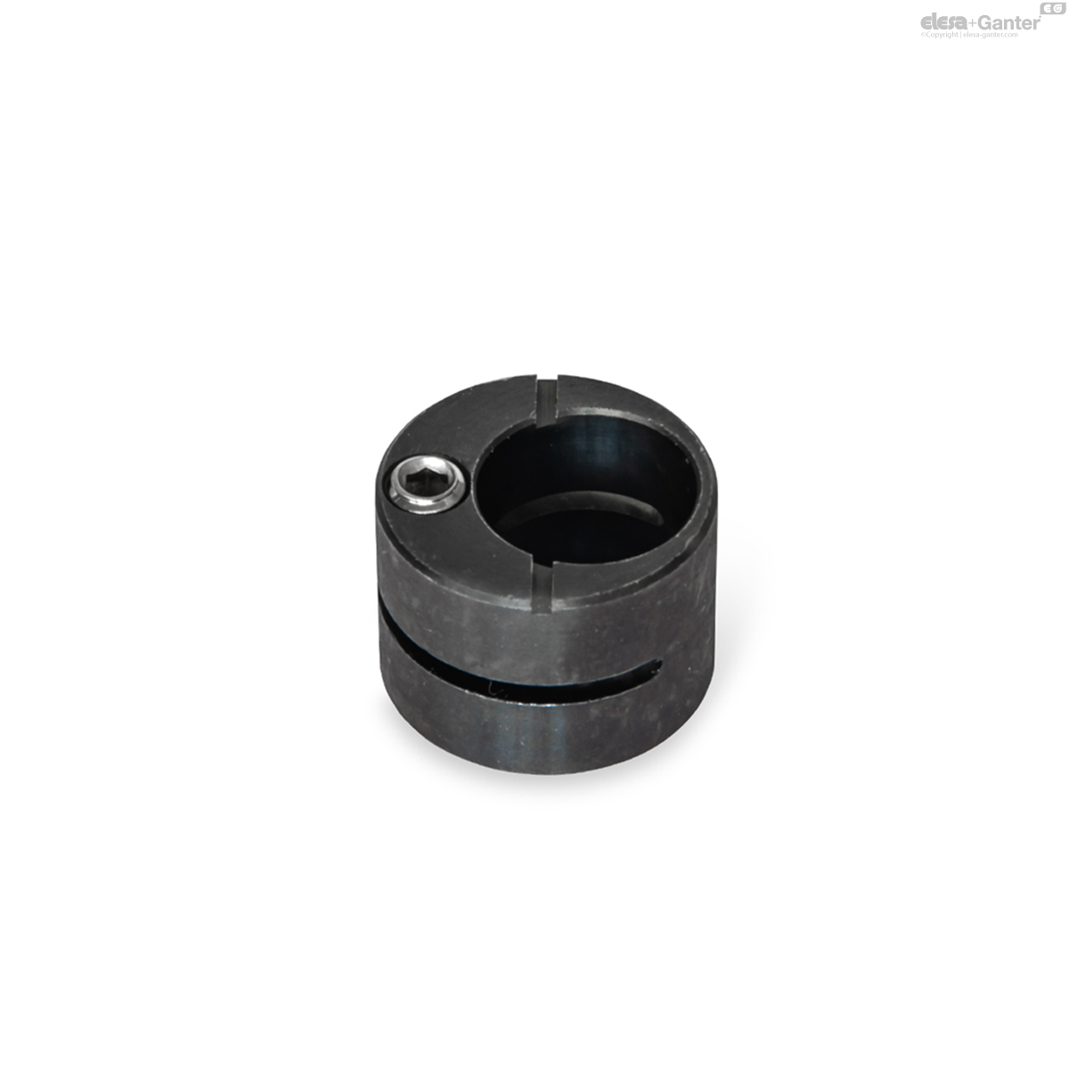
Housing
Zinc die casting ZD
plastic coated
black, RAL 9005, matte, textured finish
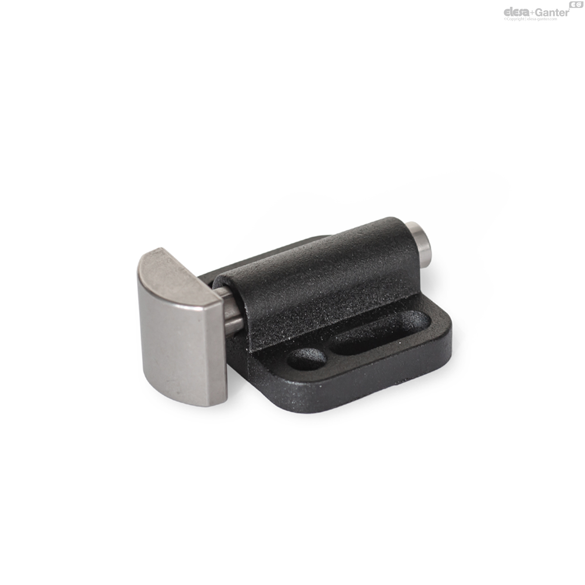
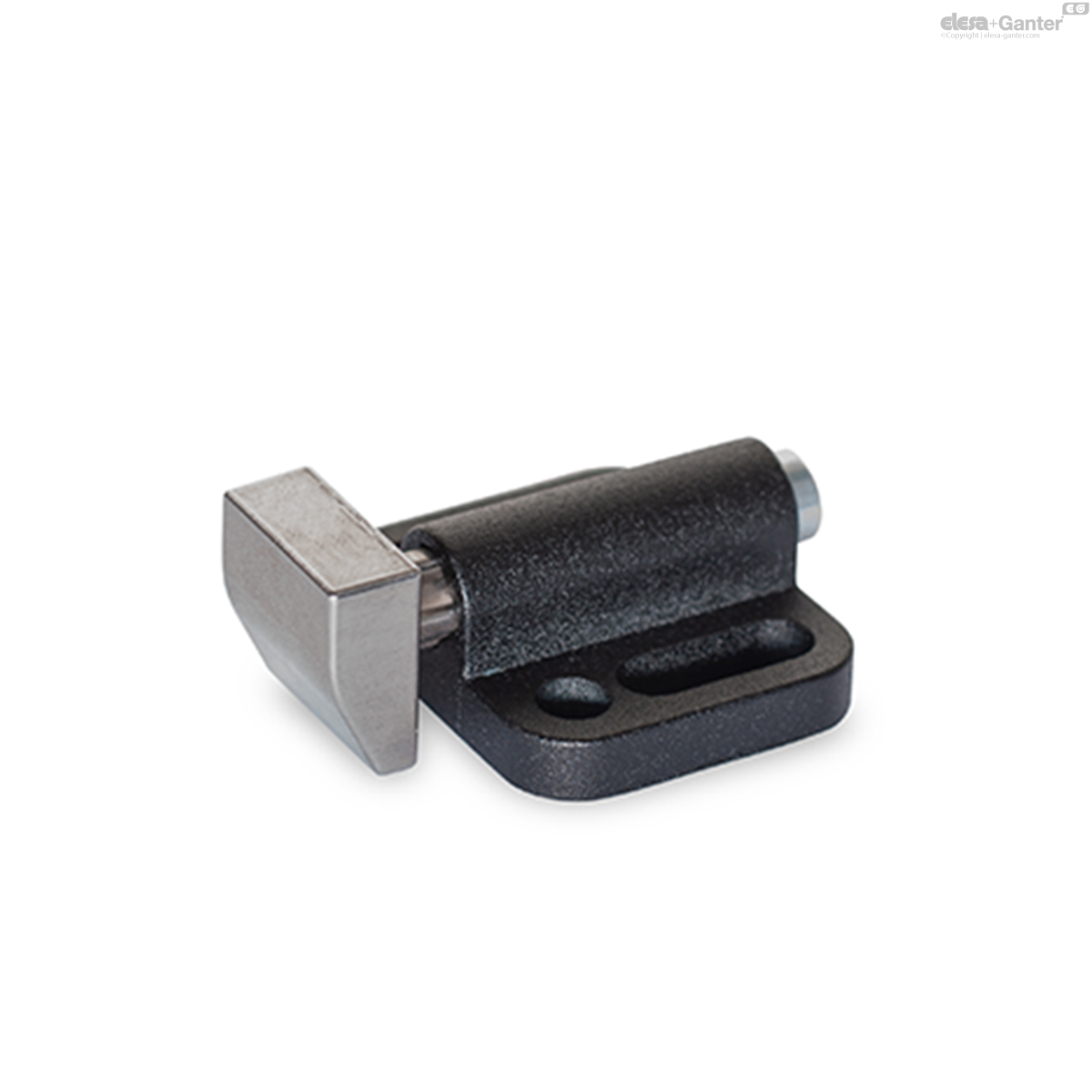
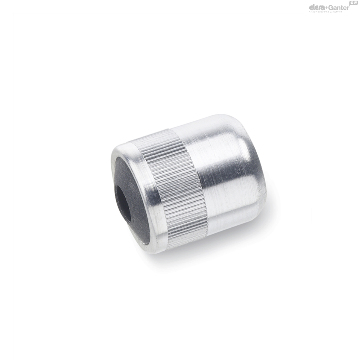
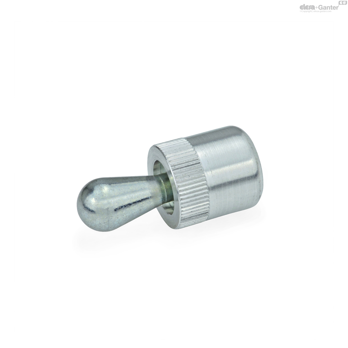
Thrust pin
Plastic, smooth KG
Plastic POM, black
Stainless Steel, smooth NG
metal injection molded AISI 630
Stainless Steel, ribbed NR
metal injection molded AISI 630
Spring
Stainless Steel AISI 301
Screw
- Steel, zinc nickel coated (Version KG)
- Stainless Steel, A2 (Version NG / NR)
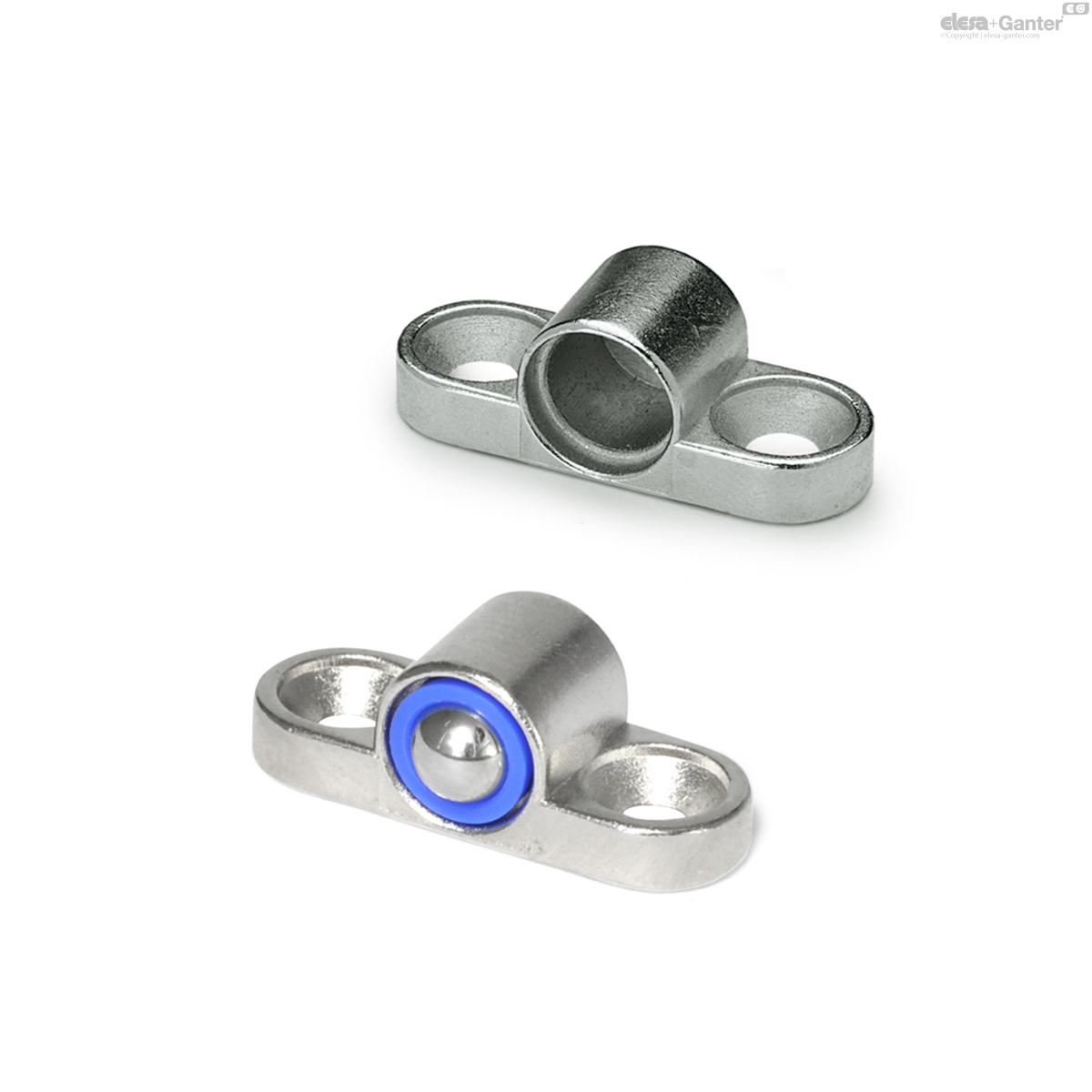
Side thrust pins GN 415 have a compact design and offer maximum flexibility for tensioning and holding parts. A variety of thrust pin designs as well as two different spring forces are available.
Depending on the installation situation, the side thrust pins offer a pull-down effect operating within height h2. They are fastened by means of holes or slots.
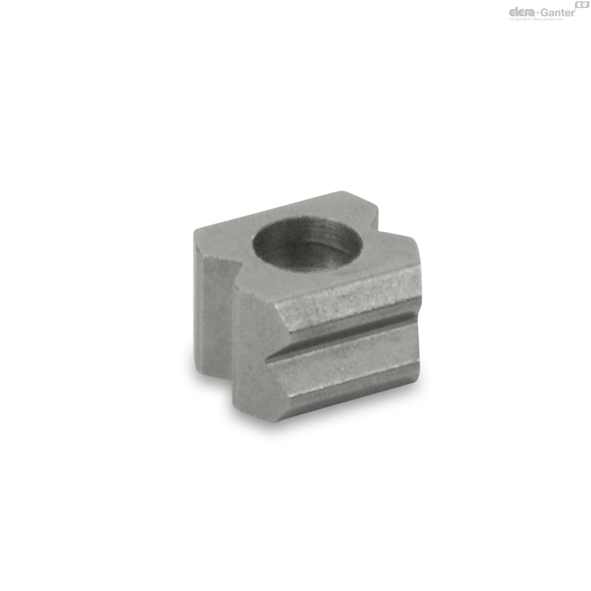
The side thrust pins are installed fully assembled. If necessary, the installation position of the thrust pin slide can be rotated by 4x90° according to the sketch. When installing version KG, the shaped thread in the plastic slider should be reused and the tightening torque limited.
Produits associés
GN 250
Blocs de retrait
pour poussoirs à ressort
GN 614.1
Poussoirs à pression latérale
GN 714
Goupilles de poussée latérales
sans goupille de pression, type à appuyer
GN 715-SA
Goupilles de poussée latérales
Appuyez sur le type
GN 715.2
Douilles excentriques
pour goupilles latérales GN 714 / GN 715
GN 716
Goupilles de poussée latérales
Appuyez sur le type