 Technical datasheet
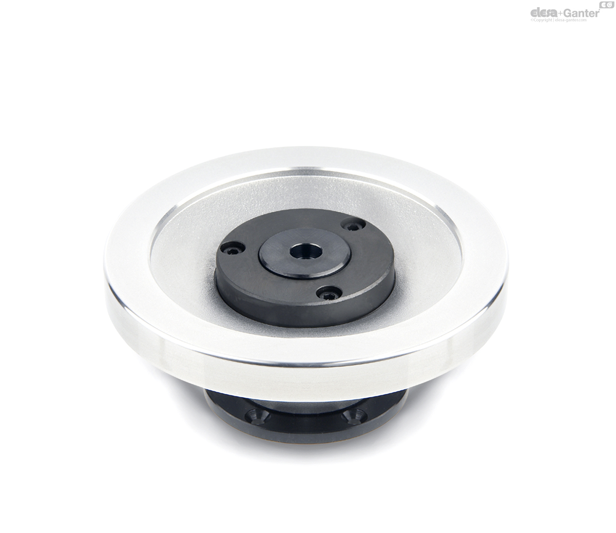
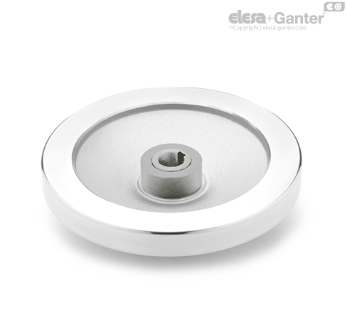
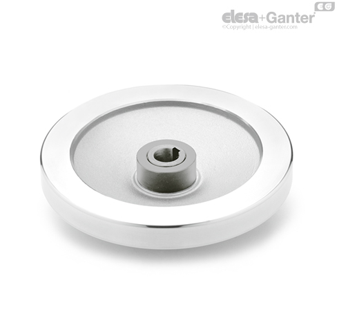
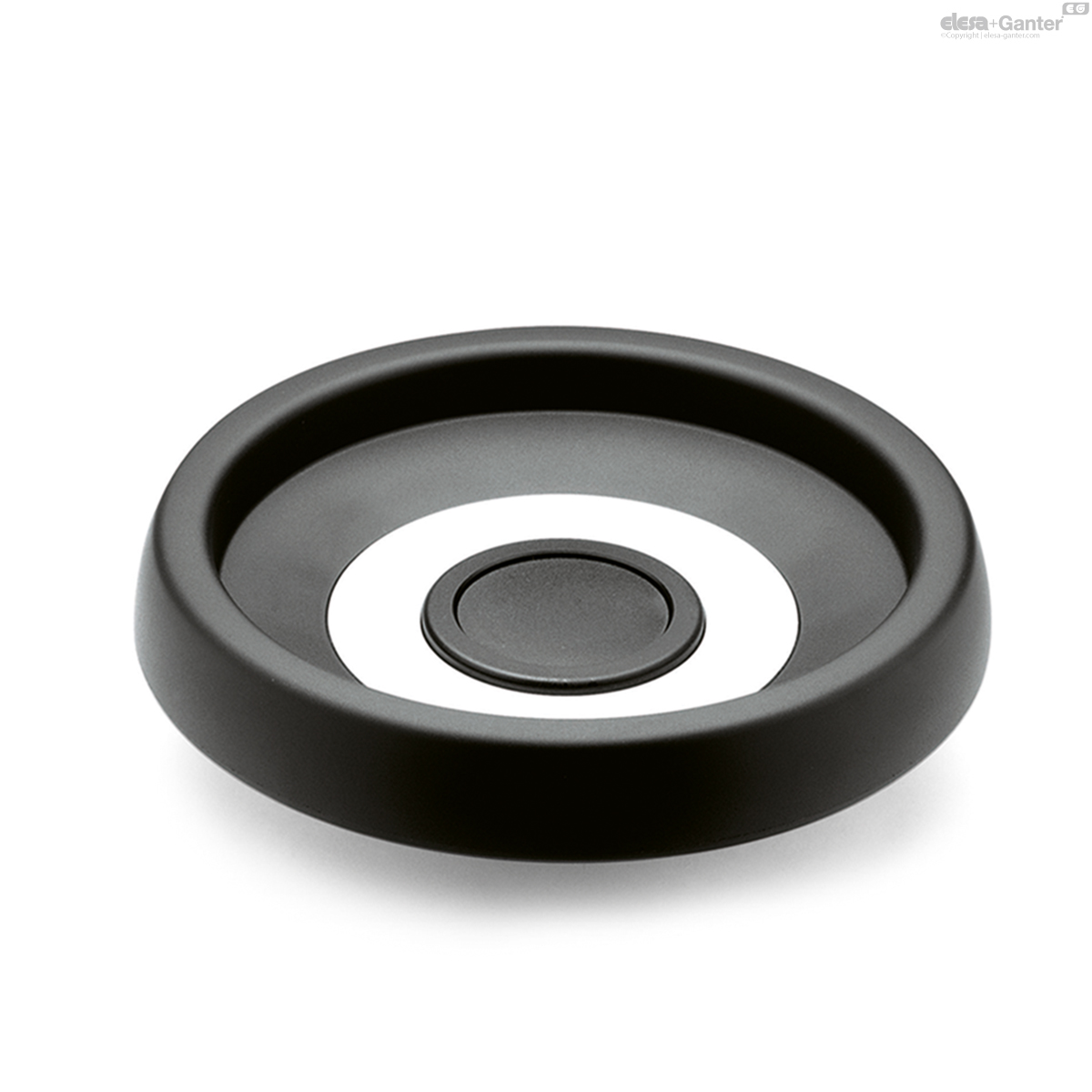
GN 327-ASafety Handwheels
Without handle
Aluminum, Fixed Bearing Flange


|
Catalogue
|
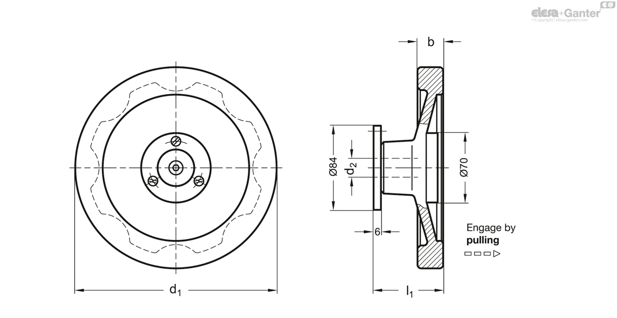
d1
|
d2 H7 Bore with keyway
|
b
|
l1
|
r
|
|
|---|---|---|---|---|---|---|
|
|
|
|
|
|
|
|
|
GN 327-160-K14-A-2
|
160
|
K 14
|
18
|
66
|
71
|
1706
|
|
GN 327-160-K16-A-2
|
160
|
K 16
|
18
|
66
|
71
|
1690
|
|
GN 327-160-K18-A-2
|
160
|
K 18
|
18
|
66
|
71
|
1670
|
|
GN 327-160-K20-A-2
|
160
|
K 20
|
18
|
66
|
71
|
1649
|
|
GN 327-200-K14-A-2
|
200
|
K 14
|
20.5
|
68
|
89
|
2047
|
|
GN 327-200-K16-A-2
|
200
|
K 16
|
20.5
|
68
|
89
|
2031
|
|
GN 327-200-K18-A-2
|
200
|
K 18
|
20.5
|
68
|
89
|
2011
|
|
GN 327-200-K20-A-2
|
200
|
K 20
|
20.5
|
68
|
89
|
1990
|
Types
Types
- Type A: Without handle
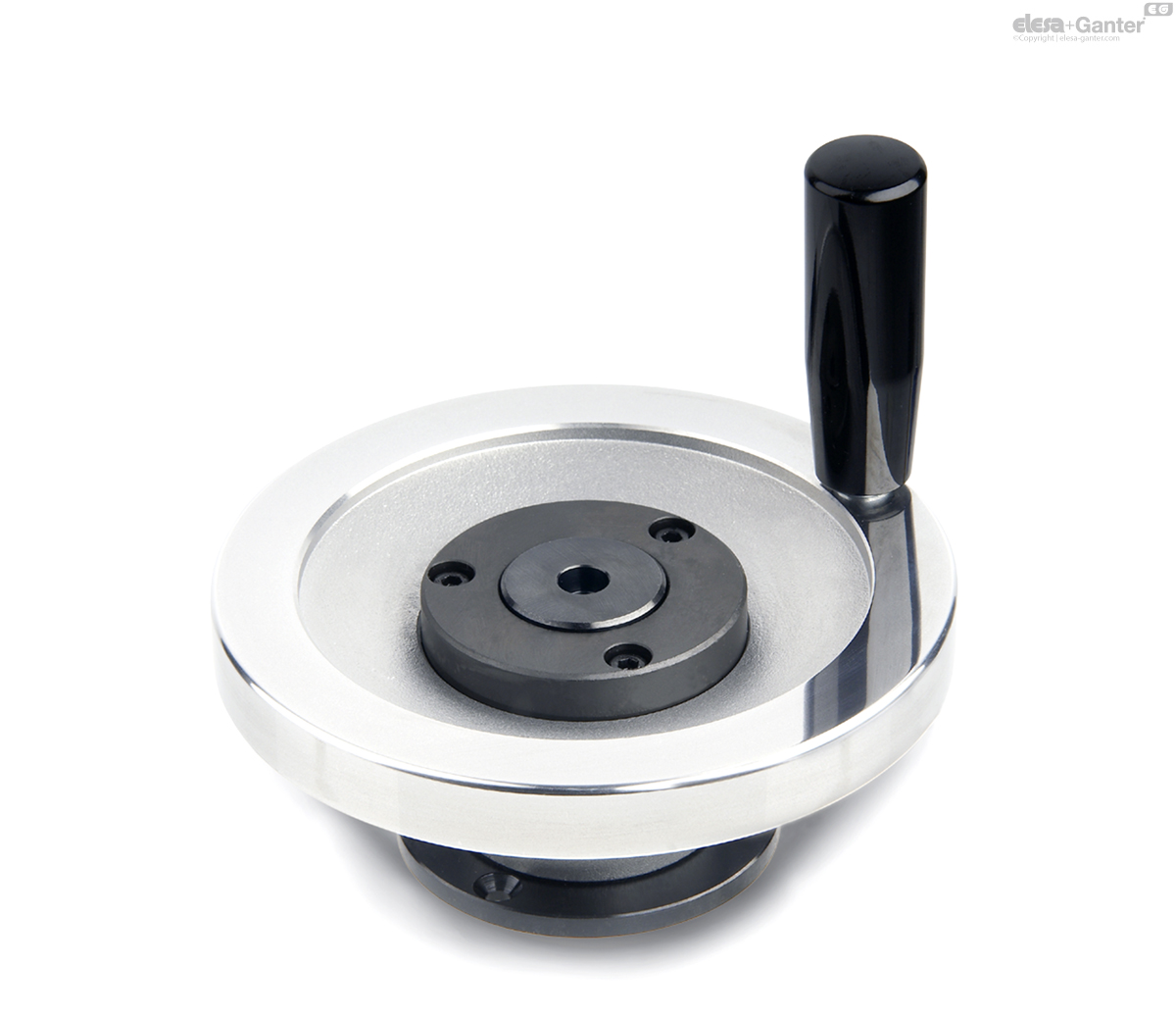
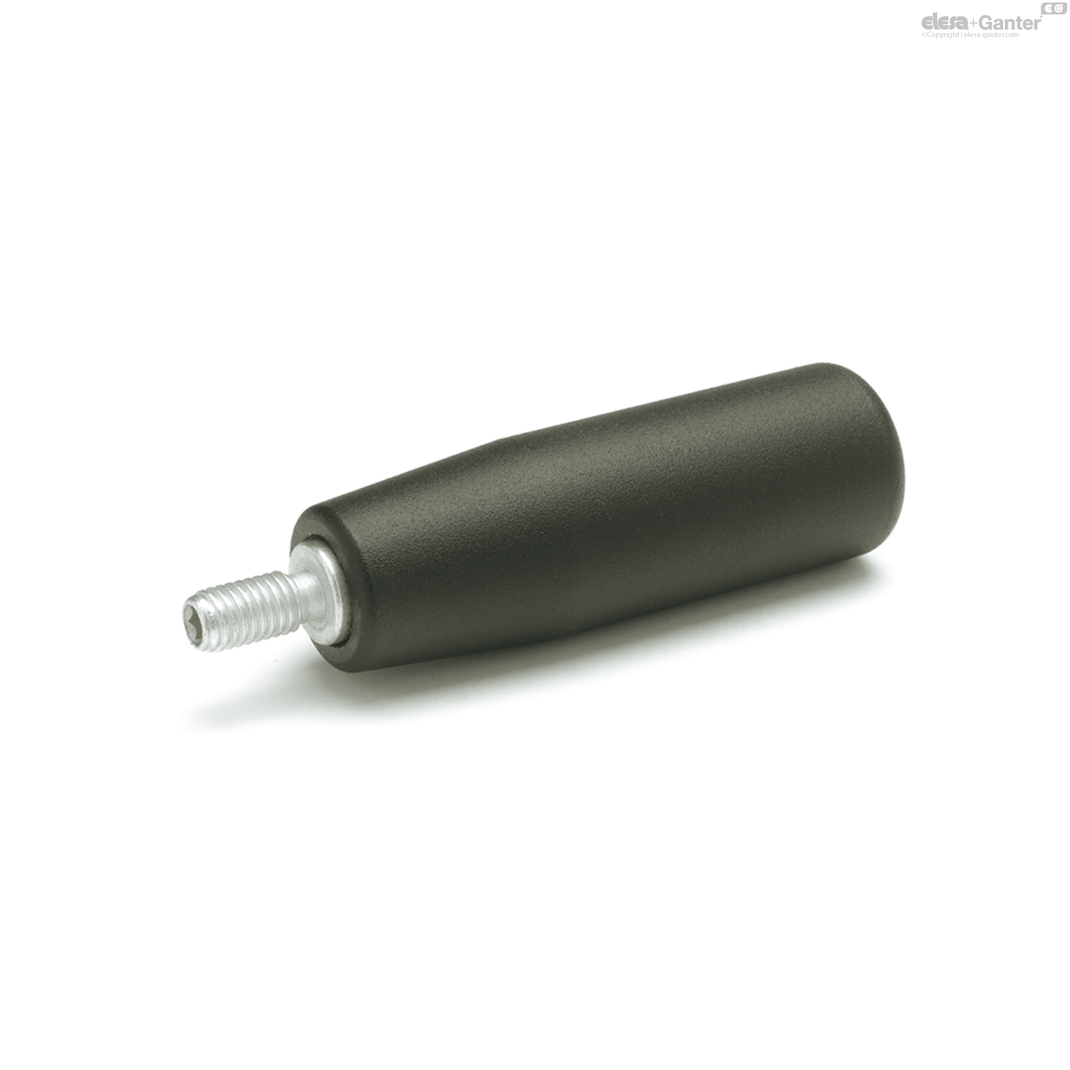
- Type D: With revolving handle
Identification no.
Identification no.
- No. 1: With bearing bushing
- No. 2: With centering ring
Wheel body
Wheel body
Aluminum
- Hub machined
- Rim
- Turned on all sides
- Highly-polished
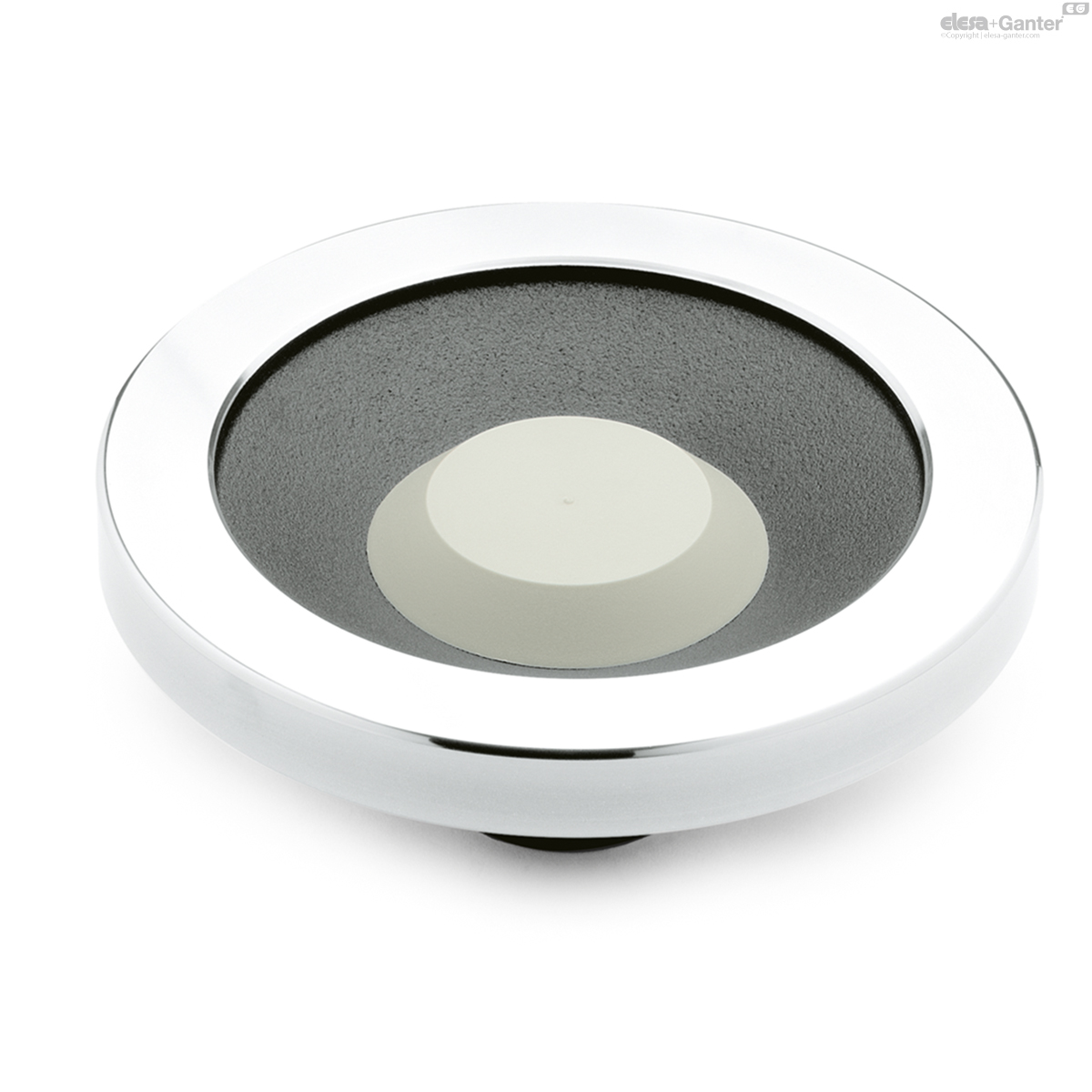
Coupling elements
Coupling elements
Steel
- Nitrided
- Bearing surface ground resp. PTFE-coated
- Bearing flange blackened
Revolving handle GN 598
Revolving handle GN 598
Plastic, phenolic resin (PF)
- Black, shiny finish
- Spindle steel
- Zinc plated, blue passivated
Safety handwheels GN 327 feature the ultimate in health and safety at work standards because the handwheel, if disengaged, is mounted on a fixed component, the bearing flange. The wheel is fully disengaged from the rotating shaft.
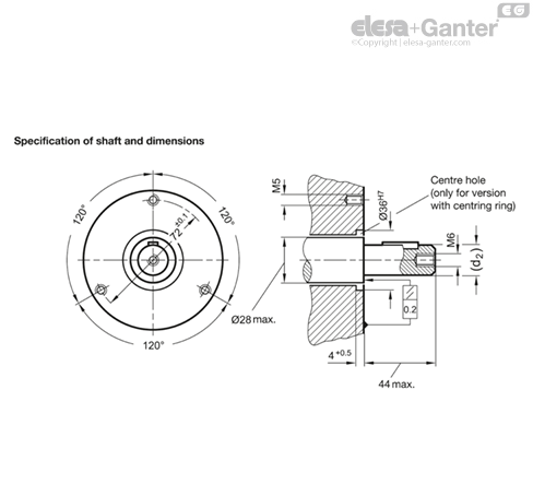
The bearing flange can also support the shaft via the bearing bushing (Identification no.1). This bearing bushing is a dry bearing (DU bushing). As a general rule, however, the shaft is supported separately and the bearing bushing is used to center the bearing flange.
Centering can also be effected by a centering ring (identification no. 2) if the appropriate bore hole has been made at the machine side. In this case there is no need for the bearing bushings and no bearing friction (heating) will occur.
- GN 184 Countersunk Washers (for Axial Fastening)
Shaft bushing and countershaft pulley are delivered in two separate components. Before assembly, make sure that the shaft bushing can be pushed smoothly and free-moving over the shaft.
Proper function is only guaranteed if on the machine side:
- the shaft collar and contact surface are level with each other
- the shaft axis is at right angles to the contact surface.
Design with bearing bushing (identification no. 1)
Push the handwheel and the shaft bushing at the same time over the shaft, bolt down the bearing flange, and fix the shaft bush axially with the countershaft pulley.
Design with centring ring (identification no. 2)
The handwheel can be bolted at once through the centring ring above the bearing flange. Then push the shaft bushing onto the shaft and fix it axially with the countershaft pulley.
Related products

DIN 950-GG-B
Handwheels
Cast Iron / Aluminum
GN 321.4-A
Safety Handwheels
Aluminum, with Friction Bearing
GN 321.5-A
Safety Handwheels
Aluminum, with Needle Bearing
GN 321.6-A
Safety Handwheels
Aluminum, with Needle Bearing
GN 598
Revolving Handles
Steel, Spindle Steel

VDN.FP-A
Solid handwheels
Duroplast, steel hub

VDS.
Solid handwheels
Technopolymer
VDT.
Solid handwheels
Technopolymer