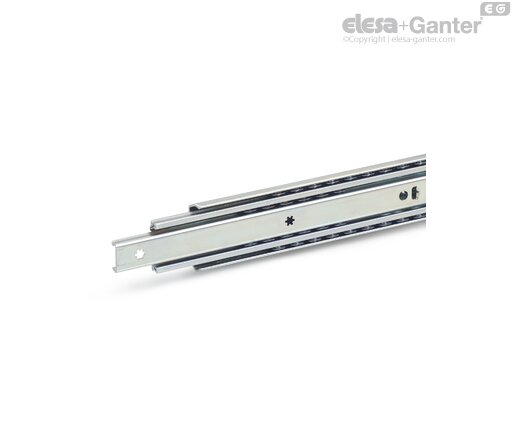
1420-550-E-2-ZB (= 1 PAIR = 2 GUIDES ) GN 1420 Telescopic Slides

Expected delivery time 5-7 working days
Prices, live stock & CAD downloads
Sign in to see your prices and stock, download CAD files and order directly online.
Sign in Request an account Technical datasheet
Technical data
- Catalogue
- GN 1420-550-E-2-ZB
- l1
- 550*
- l2 +4/-4
- 600
- l3
- 1150
- Fs per pair in N
at 10,000 cycles - 1180
- Fs per pair in N
at 100,000 cycles - 900

- 3110

Type
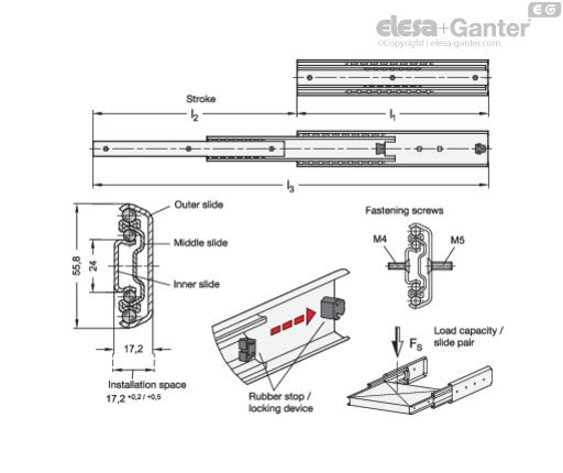
Type E: with rubber stop, locking device in back
Identification no.
No. 2: Fastening using countersunk holes
Slide profile
Steel, zinc plated, blue passivated ZB
Bearings
Roller bearing steel, hardened
Ball cage
Steel, zinc plated
Rubber stop
Plastic / Elastomer
Operating temperature -20 °C to 100 °C
Telescopic slides GN 1420 are installed vertically and in pairs. The stroke reaches ≈ 100 % of the nominal length l1 (full extension). The rubber stops of type E dampen the impact of the slide in the two end positions and takes on the locking function of the back stop position. This feature is noticeable through a slight resistance on opening and closing. If larger static or dynamic loads occur in the direction of extension, they should be absorbed by external stop elements.
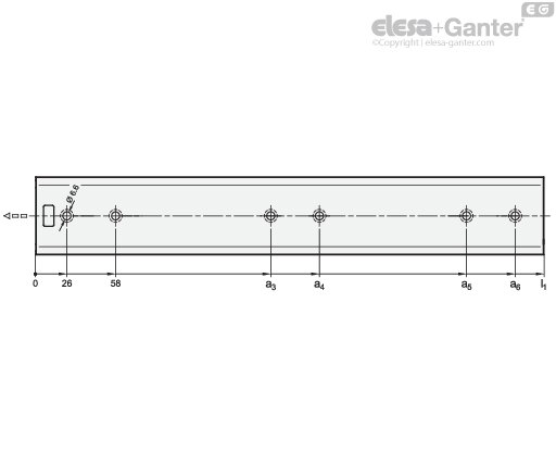
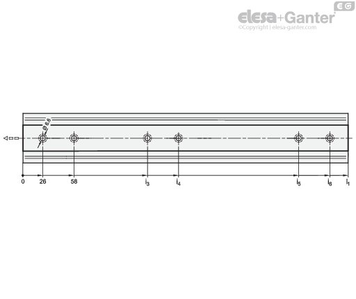
The telescopic slides are delivered in pairs. They can be installed on the extension on either the left or right side due to the mechanics. All mounting holes are easy to reach through auxiliary holes. Only the mounting holes are shown, but other production-related holes may be present.
- other lengths and hole spacing
- other attachment options
- with latches, partially with detach function (back, front, or back-front)
- with locking device (front or back-front)
- other surfaces
- with support bracket
Mounting Holes - Outer Slide
| l1 | a3 | a4 | a5 | a6 |
| 250 | 168 | 200 | - | - |
| 300 | 218 | 250 | - | - |
| 350 | 250 | 282 | - | - |
| 400 | 186 | 218 | 314 | 346 |
| 450 | 218 | 250 | 378 | 410 |
| 500 | 218 | 250 | 410 | 442 |
| 550 | 282 | 314 | 474 | 506 |
| 600 | 282 | 314 | 506 | 538 |
| 650 | 314 | 346 | 570 | 602 |
| 700 | 314 | 346 | 605 | 634 |
| 750 | 346 | 378 | 666 | 698 |
| 800 | 378 | 410 | 698 | 730 |
Mounting Holes - Inner Slide
| l1 | i3 | i4 | i5 | i6 |
| 250 | 168 | 200 | - | - |
| 300 | 218 | 250 | - | - |
| 350 | 250 | 282 | - | - |
| 400 | 154 | 186 | 314 | 346 |
| 450 | 154 | 186 | 378 | 410 |
| 500 | 186 | 218 | 410 | 442 |
| 550 | 250 | 282 | 474 | 506 |
| 600 | 250 | 282 | 506 | 538 |
| 650 | 282 | 314 | 570 | 602 |
| 700 | 314 | 346 | 602 | 634 |
| 750 | 346 | 378 | 666 | 698 |
| 800 | 346 | 378 | 698 | 730 |
Mounting Screws
For the said loading forces FS to be absorbed reliably in the surrounding structure, all available countersunk holes of the outer and inner slide must be used. Failure to use fastening screws reduces the specified load capacity accordingly. The following screws can be used for mounting:
| Designation - standard | Outer slide | Inner slide |
| Hex socket countersunk head screw DIN 7991 | M 5 | M 5 |
| Countersunk screw, Phillips DIN 965 | M 5 | M 5 |
| Countersunk screw, Phillips DIN 7997 | Size 5 | Size 5 |