 Technical
datasheet
Technical
datasheet
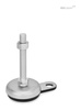
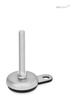
Edelstahl, mit Gummiauflage, mit Befestigungslasche

|
Catalogue
|
d1
|
d2
|
l1
|
h1
|
h3
|
l8
|
l9
|
A/F 1
|
|
|---|---|---|---|---|---|---|---|---|---|
|
|
|
|
|
|
|
|
|
|
|
|
GN 33-50-M8-40-B1-S
|
50
|
M 8
|
40
|
18
|
26
|
25
|
45
|
17
|
120
|
|
GN 33-50-M8-50-B1-S
|
50
|
M 8
|
50
|
18
|
26
|
25
|
45
|
17
|
140
|
|
GN 33-50-M8-63-B1-S
|
50
|
M 8
|
63
|
18
|
26
|
25
|
45
|
17
|
140
|
|
GN 33-50-M10-50-B1-S
|
50
|
M 10
|
50
|
18
|
26
|
25
|
45
|
17
|
150
|
|
GN 33-50-M10-60-B1-S
|
50
|
M 10
|
60
|
18
|
26
|
25
|
45
|
17
|
170
|
|
GN 33-50-M10-80-B1-S
|
50
|
M 10
|
80
|
18
|
26
|
25
|
45
|
17
|
160
|
|
GN 33-50-M10-100-B1-S
|
50
|
M 10
|
100
|
18
|
26
|
25
|
45
|
17
|
166
|
|
GN 33-50-M12-60-B1-S
|
50
|
M 12
|
60
|
18
|
26
|
25
|
45
|
17
|
160
|
|
GN 33-50-M12-80-B1-S
|
50
|
M 12
|
80
|
18
|
26
|
25
|
45
|
17
|
180
|
|
GN 33-50-M12-100-B1-S
|
50
|
M 12
|
100
|
18
|
26
|
25
|
45
|
17
|
180
|
|
GN 33-50-M12-125-B1-S
|
50
|
M 12
|
125
|
18
|
26
|
25
|
45
|
17
|
200
|
|
GN 33-60-M8-40-B1-S
|
60
|
M 8
|
40
|
19
|
27
|
25
|
50
|
17
|
286
|
|
GN 33-60-M8-50-B1-S
|
60
|
M 8
|
50
|
19
|
27
|
25
|
50
|
17
|
289
|
|
GN 33-60-M8-63-B1-S
|
60
|
M 8
|
63
|
19
|
27
|
25
|
50
|
17
|
293
|
|
GN 33-60-M10-50-B1-S
|
60
|
M 10
|
50
|
19
|
27
|
25
|
50
|
17
|
261
|
|
GN 33-60-M10-60-B1-S
|
60
|
M 10
|
60
|
19
|
27
|
25
|
50
|
17
|
200
|
|
GN 33-60-M10-80-B1-S
|
60
|
M 10
|
80
|
19
|
27
|
25
|
50
|
17
|
225
|
|
GN 33-60-M10-100-B1-S
|
60
|
M 10
|
100
|
19
|
27
|
25
|
50
|
17
|
250
|
|
GN 33-60-M12-60-B1-S
|
60
|
M 12
|
60
|
19
|
27
|
25
|
50
|
17
|
206
|
|
GN 33-60-M12-80-B1-S
|
60
|
M 12
|
80
|
19
|
27
|
25
|
50
|
17
|
190
|
|
GN 33-60-M12-100-B1-S
|
60
|
M 12
|
100
|
19
|
27
|
25
|
50
|
17
|
235
|
|
GN 33-60-M12-125-B1-S
|
60
|
M 12
|
125
|
19
|
27
|
25
|
50
|
17
|
260
|
|
GN 33-80-M8-40-B1-S
|
80
|
M 8
|
40
|
20
|
28
|
30
|
70
|
17
|
393
|
|
GN 33-80-M8-50-B1-S
|
80
|
M 8
|
50
|
20
|
28
|
30
|
70
|
17
|
150
|
|
GN 33-80-M8-63-B1-S
|
80
|
M 8
|
63
|
20
|
28
|
30
|
70
|
17
|
400
|
|
GN 33-80-M10-50-B1-S
|
80
|
M 10
|
50
|
20
|
28
|
30
|
70
|
17
|
320
|
|
GN 33-80-M10-60-B1-S
|
80
|
M 10
|
60
|
20
|
28
|
30
|
70
|
17
|
431
|
|
GN 33-80-M10-80-B1-S
|
80
|
M 10
|
80
|
20
|
28
|
30
|
70
|
17
|
350
|
|
GN 33-80-M10-100-B1-S
|
80
|
M 10
|
100
|
20
|
28
|
30
|
70
|
17
|
340
|
|
GN 33-80-M12-60-B1-S
|
80
|
M 12
|
60
|
20
|
28
|
30
|
70
|
17
|
445
|
|
GN 33-80-M12-80-B1-S
|
80
|
M 12
|
80
|
20
|
28
|
30
|
70
|
17
|
340
|
|
GN 33-80-M12-100-B1-S
|
80
|
M 12
|
100
|
20
|
28
|
30
|
70
|
17
|
340
|
|
GN 33-80-M12-125-B1-S
|
80
|
M 12
|
125
|
20
|
28
|
30
|
70
|
17
|
380
|
|
GN 33-100-M8-40-B1-S
|
100
|
M 8
|
40
|
21
|
29
|
30
|
80
|
17
|
557
|
|
GN 33-100-M8-50-B1-S
|
100
|
M 8
|
50
|
21
|
29
|
30
|
80
|
17
|
560
|
|
GN 33-100-M8-63-B1-S
|
100
|
M 8
|
63
|
21
|
29
|
30
|
80
|
17
|
564
|
|
GN 33-100-M10-50-B1-S
|
100
|
M 10
|
50
|
21
|
29
|
30
|
80
|
17
|
590
|
|
GN 33-100-M10-60-B1-S
|
100
|
M 10
|
60
|
21
|
29
|
30
|
80
|
17
|
451
|
|
GN 33-100-M10-80-B1-S
|
100
|
M 10
|
80
|
21
|
29
|
30
|
80
|
17
|
604
|
|
GN 33-100-M10-100-B1-S
|
100
|
M 10
|
100
|
21
|
29
|
30
|
80
|
17
|
615
|
|
GN 33-100-M12-60-B1-S
|
100
|
M 12
|
60
|
21
|
29
|
30
|
80
|
17
|
500
|
|
GN 33-100-M12-80-B1-S
|
100
|
M 12
|
80
|
21
|
29
|
30
|
80
|
17
|
622
|
|
GN 33-100-M12-100-B1-S
|
100
|
M 12
|
100
|
21
|
29
|
30
|
80
|
17
|
637
|
|
GN 33-100-M12-125-B1-S
|
100
|
M 12
|
125
|
21
|
29
|
30
|
80
|
17
|
520
|
Fußteller / Lasche
Edelstahl 1.4301
Gewindespindel
Edelstahl 1.4305
Sechskantmutter ISO 4032
Edelstahl 1.4301
Gummiauflage eingelegt
schwarz, NBR (Perbunan®)
80±5 Shore A
Stellfüße GN 33 werden montiert geliefert; sie sind nicht demontierbar.

Die in der Tabelle angegebene Belastbarkeit beruht auf Versuchsreihen, bei der eine Last senkrecht zum Fußteller aufgebracht wurde. Bei diesen Werten kann es nach der Entlastung bereits zu geringfügigen, bleibenden Verformungen des Blechtellers kommen.
Die in der Praxis häufig auftretenden Biege- und Knickbeanspruchungen führen zu einer Minderung der Belastbarkeit der Verstellspindel und sind gegebenenfalls zu berücksichtigen.
Im übrigen wird eine Spindelfestigkeit ≥ 500 N/mm2 zugrunde gelegt.
Die Angaben über die Belastbarkeit sind unverbindliche Richtwerte unter Ausschluss jeglicher Haftung. Sie stellen generell keine Beschaffenheitszusage dar.
Ob ein Produkt für den jeweiligen Einsatzfall geeignet ist, muss in jedem Einzelfall vom Anwender ermittelt werden. Umgebungseinflüsse können die angegebenen Werte beeinflussen.
| d1 | d2 | Statische Last in kN | - | - | - | - |
| - | - | Spindelvarianten | - | - | - | - |
| - | - | S / SK | T / TK und U / UK | V / VK | W | X |
| - | - | Gummi schwarz | Gummi schwarz | Gummi schwarz | Gummi schwarz | Gummi schwarz |
| 50 | M 8 | 8 | - | - | - | 8 |
| 50 | M 10 | 14 | - | - | - | 13 |
| 50 | M 12 | 20 | - | - | - | 20 |
| 50 | M 16 | - | 28 | - | - | 28 |
| 60 | M 8 | 8 | - | - | - | 8 |
| 60 | M 10 | 14 | - | - | - | 13 |
| 60 | M 12 | 20 | - | - | - | 20 |
| 60 | M 16 | - | 28 | 27 | 27 | 28 |
| 80 | M 8 | 8 | - | - | - | 8 |
| 80 | M 10 | 14 | - | - | - | 13 |
| 80 | M 12 | 19 | - | - | - | 15 |
| 80 | M 16 | - | 19 | 24 | 24 | 19 |
| 80 | M 20 | - | 19 | 24 | 24 | 19 |
| 80 | M 24 | - | 19 | 24 | 24 | - |
| 100 | M 8 | 8 | - | - | - | 8 |
| 100 | M 10 | 14 | - | - | - | 13 |
| 100 | M 12 | 17 | - | - | - | 17 |
| 100 | M 16 | - | 17 | 21 | 21 | 17 |
| 100 | M 20 | - | 17 | 21 | 21 | 17 |
| 100 | M 24 | - | 17 | 21 | 21 | - |
| 120 | M 20 | - | 25 | - | - | 25 |
| 120 | M 24 | - | 25 | - | - | - |
| 120 | M 30 | - | 25 | - | - | - |
| Spindelvarianten | ||
| S / SK: Außensechskant unten bei d2 M 8, M 10, M 12 | T / TK: Schlüsselfläche unten bei d2 M 16, M 20, M 24, M 30 | U / UK: Innensechskant oben und Schlüsselfläche unten bei d2 M 16, M 20, M 24, M30 |
| V / VK: Außensechskant oben und Schlüsselfläche unten bei d2 M 16, M 20, M 24 | W: Abgedecktes Gewinde und Schlüsselfläche unten bei d2 M 16, M20, M24 | X: Außensechskant mit Innengewinde bei d2 M 8, M 10, M 12, M 16, M 20 |


