


 Technical datasheet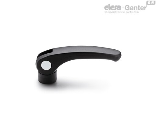
LAC-BCam clamping levers
Without adjustable ring-nut, rotating pin with zinc-plated steel threaded hole
Technopolymer




LAC-B
|
Catalogue
|
Description
|
R
|
d
|
D
|
h
|
h1 max
|
h2
|
d1
|
d3
|
l1
|
x
|
Fmax*
[N] |
|
|---|---|---|---|---|---|---|---|---|---|---|---|---|---|
|
LAC.44-B-M5
|
44
|
M5
|
17.5
|
18
|
20.5
|
5.5
|
6.1
|
9
|
18
|
0.5
|
3500
| ||
|
LAC.44-B-M6
|
44
|
M6
|
17.5
|
18
|
20.5
|
5.5
|
6.1
|
9
|
18
|
0.5
|
3500
| ||
|
LAC.63-B-M5
|
63
|
M5
|
17.5
|
18
|
20.5
|
5.5
|
6.1
|
9
|
18
|
0.75
|
4000
| ||
|
LAC.63-B-M6
|
63
|
M6
|
17.5
|
18
|
20.5
|
5.5
|
6.1
|
9
|
18
|
0.75
|
4000
| ||
|
LAC.80-B-M6
|
79
|
M6
|
20
|
21
|
25.5
|
7
|
8.1
|
11
|
20
|
1
|
7000
| ||
|
LAC.80-B-M8
|
79
|
M8
|
20
|
21
|
25.5
|
7
|
8.1
|
11
|
20
|
1
|
7000
|
* Maximum clamping force.


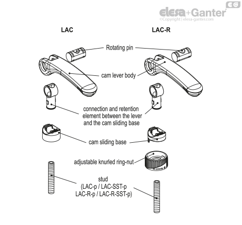
Cam lever body
Glass-fibre reinforced polyamide based (PA) technopolymer, black colour, matte finish.
Rotating pin
Glossy zinc-plated steel or AISI 303 stainless steel, with threaded hole or threaded stud.
Connection and retention element between the lever and the cam sliding base
Polyamide based (PA) technopolymer, black colour.
Cam sliding base
Polyamide-based SUPER-technopolymer (PA), black colour.
Adjustable knurled ring-nut
Polyamide-based SUPER-technopolymer (PA), black colour.
Standard executions
- LAC-B: positioning without adjustable ring-nut, rotating pin with zinc-plated steel threaded hole.
- LAC-SST: positioning without adjustable ring-nut, rotating pin with AISI 303 stainless steel threaded hole.
- LAC-p: positioning without adjustable ring-nut, rotating pin with zinc-plated steel threaded stud, chamfered flat end UNI 947: ISO 4753 Technical data).
- LAC-SST-p: positioning without adjustable ring-nut, rotating pin with AISI 303 stainless steel threaded stud, chamfered flat end UNI 947: ISO 4753 Technical data).
- LAC-B-R: positioning with adjustable ring-nut, rotating pin with zinc-plated steel threaded hole.
- LAC-SST-R: positioning with adjustable ring-nut, rotating pin with AISI 303 stainless steel threaded hole.
- LAC-p-R: positioning with adjustable ring-nut, rotating pin with threaded stud in zinc-plated steel, chamfered flat end UNI 947: ISO 4753 (see Technical data).
- LAC-SST-p-R: positioning with adjustable ring-nut, rotating pin with threaded stud in AISI 303 stainless steel, chamfered flat end UNI 947: ISO 4753Technical data).
Features and applications
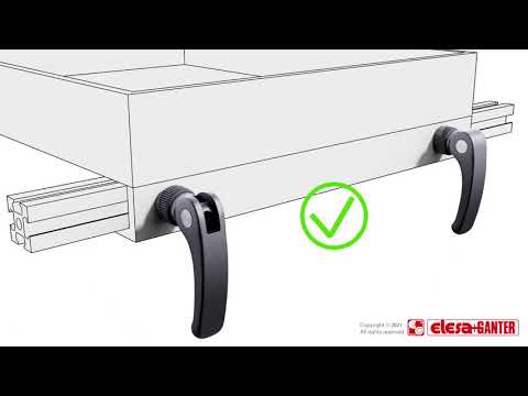
Cam lever is a device which allows a quick and secure clamping.
The LAC-R model with adjustable ring-nut (ELESA patent) offers quick and secure clamping. The knurled ring-nut on the base allows to adjust the clamping force applied while locking the lever in the desired position.
Special executions on request
Cam clamps with connection element, not drilled for a better cleaning (for sufficient quantities).
Recommendations for assembly
LAC-B, LAC-SST, LAC-B-R and LAC-SST-R with threaded hole. The screw where the cam lever is mounted must protrude from the assembly surface by a maximum length of h1 max from the end-stop as shown in table and Fig.1. The user will notice the h1 max value is reached as the screw rests on the end-stop in the connecting element.
Instructions for clamping and adjustment
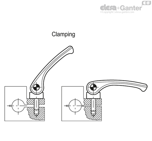
- LAC: lift and rotate the lever clockwise until it stops, then, to complete clamping, lower the lever whose fulcrum is an eccentric cam which controls the base by rotating.
- LAC-R: rotate the lever clockwise until it stops.
Fine adjustment: rotate clockwise or anti-clockwise the knurled adjustable ring-nut to calibrate the clamping force and put the lever in the desired position. The ring-nut is marked with minimum and maximum adjustment values: half a turn is enough for adjustment.
Clamping: lower the lever whose fulcrum is an eccentric cam which controls the adjusting base by rotating.
Related products
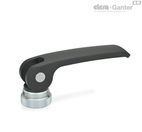
GN 927-A
Clamping Levers with Eccentrical Cam
Lever Zinc Die Casting, Contact Plate Plastic, with Internal Thread / with Threaded Stud
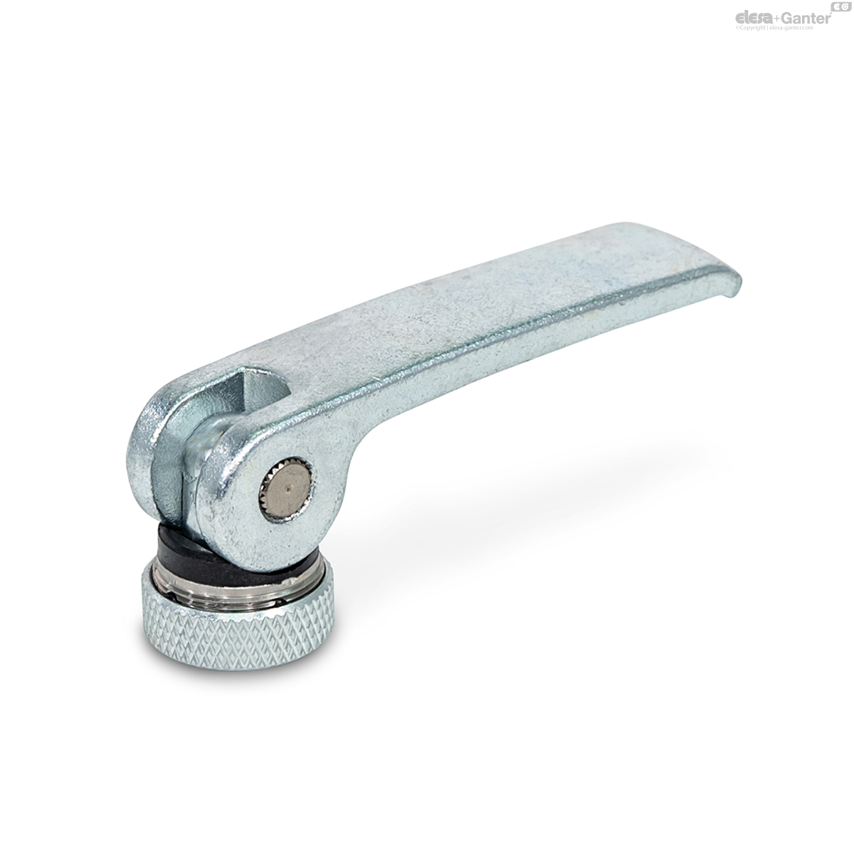
GN 927.3-A
Clamping Levers with Eccentrical Cam
Lever Steel, Contact Plate Plastic, with Internal Thread / with Threaded Stud

GN 927.4-A
Clamping Levers with Eccentrical Cam
Lever Zinc Die Casting, Contact Plate Plastic, with Internal Thread / with Threaded Stud

GN 927.7-A
Clamping Levers with Eccentrical Cam
Stainless Steel, with Internal Thread / with Threaded Stud