Technical
datasheet
Technical
datasheet
Locking Distance A1 / A2 Adjustable


|
Catalogue
|
Locking Distance Nominal size
|
A min.
|
l1
|
w Adjustable range
|
|
|---|---|---|---|---|---|
|
|
|
|
|
|
|
|
GN 315-A1
|
A 1
|
18
|
52
|
5
|
100
|
Housing
Zinc die casting
ZNDG Pass. nano®-coating
Setting sleeve
Steel
Powder coated
Black, matte textured finish
Operating button / Slide
Plastic (Polyamide PA)
Black, matte finish
Push button
Plastic (Polyamide PA)
Light gray
Hex nut
Steel
Zinc plated, blue passivated
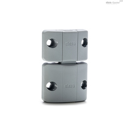
Snap locks GN 315 are characterized by a radial, spring-loaded slide causing the locking action.
When closing the door, the locking action sets in automatically. The bevelled slide is first pushed back via an appropriately arranged lug and then moved into the locking position by the pressure spring.
The door is unlocked via the push button.
To operate the door, these snap locks are fitted with an operating button.

These snap locks can be used to latch a door, cover or hatch but not to clamp it.
This is why it is important to position the locking distance A (door + door frame thickness) with great accuracy and precision.
For snap locks GN 315, the locking distance can be set continuously via the setting sleeve adjustable via a precision thread. This makes installation a great deal easier.
For installation, set a hole in the door, cover or hatch as shown in the outline drawing.
The snap lock is inserted through the hole from the front. The mounting nut is then simply pushed onto the slide from the back side and screwed into place.
The required installation bore in the door leaf, is usually generated by punching or laser machining in series production.
The installation bore diameter can also be created by drilling or milling as shown in the outline drawings.
For small series and steel sheets below 2 mm thickness, the sheet metal punches GN 123 are the tool of choice.