Technical
datasheet
Technical
datasheet
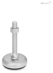
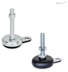
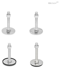
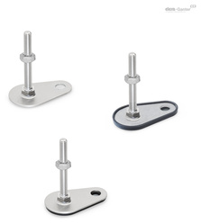
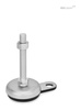
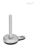
Roestvrij staal, met rubberen pad, met montageflens

|
Code
|
d1
|
d2
|
l1
|
h1
|
h3
|
l8
|
l9
|
A/F 1
|
|
|---|---|---|---|---|---|---|---|---|---|
|
|
|
|
|
|
|
|
|
|
|
|
GN 33-50-M8-40-B1-S
|
50
|
M 8
|
40
|
18
|
26
|
25
|
45
|
17
|
120
|
|
GN 33-50-M8-50-B1-S
|
50
|
M 8
|
50
|
18
|
26
|
25
|
45
|
17
|
140
|
|
GN 33-50-M8-63-B1-S
|
50
|
M 8
|
63
|
18
|
26
|
25
|
45
|
17
|
140
|
|
GN 33-50-M10-50-B1-S
|
50
|
M 10
|
50
|
18
|
26
|
25
|
45
|
17
|
150
|
|
GN 33-50-M10-60-B1-S
|
50
|
M 10
|
60
|
18
|
26
|
25
|
45
|
17
|
170
|
|
GN 33-50-M10-80-B1-S
|
50
|
M 10
|
80
|
18
|
26
|
25
|
45
|
17
|
160
|
|
GN 33-50-M10-100-B1-S
|
50
|
M 10
|
100
|
18
|
26
|
25
|
45
|
17
|
166
|
|
GN 33-50-M12-60-B1-S
|
50
|
M 12
|
60
|
18
|
26
|
25
|
45
|
17
|
160
|
|
GN 33-50-M12-80-B1-S
|
50
|
M 12
|
80
|
18
|
26
|
25
|
45
|
17
|
180
|
|
GN 33-50-M12-100-B1-S
|
50
|
M 12
|
100
|
18
|
26
|
25
|
45
|
17
|
180
|
|
GN 33-50-M12-125-B1-S
|
50
|
M 12
|
125
|
18
|
26
|
25
|
45
|
17
|
200
|
|
GN 33-60-M8-40-B1-S
|
60
|
M 8
|
40
|
19
|
27
|
25
|
50
|
17
|
286
|
|
GN 33-60-M8-50-B1-S
|
60
|
M 8
|
50
|
19
|
27
|
25
|
50
|
17
|
289
|
|
GN 33-60-M8-63-B1-S
|
60
|
M 8
|
63
|
19
|
27
|
25
|
50
|
17
|
293
|
|
GN 33-60-M10-50-B1-S
|
60
|
M 10
|
50
|
19
|
27
|
25
|
50
|
17
|
261
|
|
GN 33-60-M10-60-B1-S
|
60
|
M 10
|
60
|
19
|
27
|
25
|
50
|
17
|
200
|
|
GN 33-60-M10-80-B1-S
|
60
|
M 10
|
80
|
19
|
27
|
25
|
50
|
17
|
225
|
|
GN 33-60-M10-100-B1-S
|
60
|
M 10
|
100
|
19
|
27
|
25
|
50
|
17
|
250
|
|
GN 33-60-M12-60-B1-S
|
60
|
M 12
|
60
|
19
|
27
|
25
|
50
|
17
|
206
|
|
GN 33-60-M12-80-B1-S
|
60
|
M 12
|
80
|
19
|
27
|
25
|
50
|
17
|
190
|
|
GN 33-60-M12-100-B1-S
|
60
|
M 12
|
100
|
19
|
27
|
25
|
50
|
17
|
235
|
|
GN 33-60-M12-125-B1-S
|
60
|
M 12
|
125
|
19
|
27
|
25
|
50
|
17
|
260
|
|
GN 33-80-M8-40-B1-S
|
80
|
M 8
|
40
|
20
|
28
|
30
|
70
|
17
|
393
|
|
GN 33-80-M8-50-B1-S
|
80
|
M 8
|
50
|
20
|
28
|
30
|
70
|
17
|
150
|
|
GN 33-80-M8-63-B1-S
|
80
|
M 8
|
63
|
20
|
28
|
30
|
70
|
17
|
400
|
|
GN 33-80-M10-50-B1-S
|
80
|
M 10
|
50
|
20
|
28
|
30
|
70
|
17
|
320
|
|
GN 33-80-M10-60-B1-S
|
80
|
M 10
|
60
|
20
|
28
|
30
|
70
|
17
|
431
|
|
GN 33-80-M10-80-B1-S
|
80
|
M 10
|
80
|
20
|
28
|
30
|
70
|
17
|
350
|
|
GN 33-80-M10-100-B1-S
|
80
|
M 10
|
100
|
20
|
28
|
30
|
70
|
17
|
340
|
|
GN 33-80-M12-60-B1-S
|
80
|
M 12
|
60
|
20
|
28
|
30
|
70
|
17
|
445
|
|
GN 33-80-M12-80-B1-S
|
80
|
M 12
|
80
|
20
|
28
|
30
|
70
|
17
|
340
|
|
GN 33-80-M12-100-B1-S
|
80
|
M 12
|
100
|
20
|
28
|
30
|
70
|
17
|
340
|
|
GN 33-80-M12-125-B1-S
|
80
|
M 12
|
125
|
20
|
28
|
30
|
70
|
17
|
380
|
|
GN 33-100-M8-40-B1-S
|
100
|
M 8
|
40
|
21
|
29
|
30
|
80
|
17
|
557
|
|
GN 33-100-M8-50-B1-S
|
100
|
M 8
|
50
|
21
|
29
|
30
|
80
|
17
|
560
|
|
GN 33-100-M8-63-B1-S
|
100
|
M 8
|
63
|
21
|
29
|
30
|
80
|
17
|
564
|
|
GN 33-100-M10-50-B1-S
|
100
|
M 10
|
50
|
21
|
29
|
30
|
80
|
17
|
590
|
|
GN 33-100-M10-60-B1-S
|
100
|
M 10
|
60
|
21
|
29
|
30
|
80
|
17
|
451
|
|
GN 33-100-M10-80-B1-S
|
100
|
M 10
|
80
|
21
|
29
|
30
|
80
|
17
|
604
|
|
GN 33-100-M10-100-B1-S
|
100
|
M 10
|
100
|
21
|
29
|
30
|
80
|
17
|
615
|
|
GN 33-100-M12-60-B1-S
|
100
|
M 12
|
60
|
21
|
29
|
30
|
80
|
17
|
500
|
|
GN 33-100-M12-80-B1-S
|
100
|
M 12
|
80
|
21
|
29
|
30
|
80
|
17
|
622
|
|
GN 33-100-M12-100-B1-S
|
100
|
M 12
|
100
|
21
|
29
|
30
|
80
|
17
|
637
|
|
GN 33-100-M12-125-B1-S
|
100
|
M 12
|
125
|
21
|
29
|
30
|
80
|
17
|
520
|
Base plate / flange
Stainless steel AISI 304
Threaded stem
Stainless steel AISI 303
Hex nut ISO 4032
Stainless steel AISI 304
Rubber pad, inlaid
Black, NBR (Perbunan®)
80±5 Shore A
Leveling feet GN 33 will be delivered mounted and are not removable.
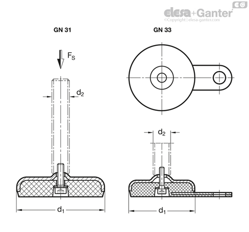
The static load bearing capacity given in the table rests on a test series in which the load has been applied perpendicular to the base plate. For the values given in the table, the strain relief may result in minor deformations of the base plate.
Bending and buckling stress which often occurs in practice results in a lower load bearing capacity of the adjustment spindle and may have to be taken into account.
Also, the spindle strength is assumed to be ≥ 500 N/mm2.
The details given on strength are nonbinding guide values without any liability. In general, they do not constitute a warranty of quality.
The user must determine from case to case if a product is suitable for the intended purpose or use. Environmental factors may influence the stated values.
| d1 | d2 | Static load in kN | - | - | - | - |
| - | - | Versions of threaded stem | - | - | - | - |
| - | - | S / SK | T / TK and U / UK | V / VK | W | X |
| - | - | Rubber black | Rubber black | Rubber black | Rubber black | Rubber black |
| 50 | M 8 | 8 | - | - | - | 8 |
| 50 | M 10 | 14 | - | - | - | 13 |
| 50 | M 12 | 20 | - | - | - | 20 |
| 50 | M 16 | - | 28 | - | - | 28 |
| 60 | M 8 | 8 | - | - | - | 8 |
| 60 | M 10 | 14 | - | - | - | 13 |
| 60 | M 12 | 20 | - | - | - | 20 |
| 60 | M 16 | - | 28 | 27 | 27 | 28 |
| 80 | M 8 | 8 | - | - | - | 8 |
| 80 | M 10 | 14 | - | - | - | 13 |
| 80 | M 12 | 19 | - | - | - | 15 |
| 80 | M 16 | - | 19 | 24 | 24 | 19 |
| 80 | M 20 | - | 19 | 24 | 24 | 19 |
| 80 | M 24 | - | 19 | 24 | 24 | - |
| 100 | M 8 | 8 | - | - | - | 8 |
| 100 | M 10 | 14 | - | - | - | 13 |
| 100 | M 12 | 17 | - | - | - | 17 |
| 100 | M 16 | - | 17 | 21 | 21 | 17 |
| 100 | M 20 | - | 17 | 21 | 21 | 17 |
| 100 | M 24 | - | 17 | 21 | 21 | - |
| 120 | M 20 | - | 25 | - | - | 25 |
| 120 | M 24 | - | 25 | - | - | - |
| 120 | M 30 | - | 25 | - | - | - |
| Versions of threaded stem | ||
| S / SK: External hex at the bottom at d2 M 8, M 10, M 12 | T / TK: Wrench flat at the bottom at d2 M 16, M 20, M 24, M 30 | U / UK: Hex socket at the top and wrench flat at the bottom at d2 M 16, M 20, M 24, M 30 |
| V / VK: External hex at the top and wrench flat at the bottom at d2 M 16, M 20, M 24 | W: Covered thread and wrench flat at the bottom at d2 M 16, M 20, M 24 | X: External hex with internal thread at d2 M 8, M 10, M 12, M 16, M 20 |