 Technical datasheet
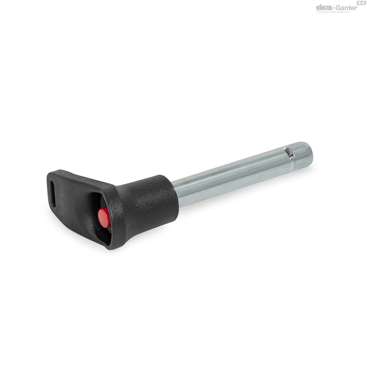
GN 114.11Borgpennen
Borgpennen
Stift staal, L-greep kunststof, met axiale vergrendeling (pal)

GN 114.11
|
Code
|
d1 -0.1
|
l1 +0.4 Minimum size
|
a
|
b
|
d2
|
d3
|
d4
|
d5
|
l2
|
l3
|
l4
|
Load capacity F in kN≈
double sided shearing resistance acc. DIN 50141 (breaking strength) |
|---|---|---|---|---|---|---|---|---|---|---|---|---|
|
|
|
|
|
|
|
|
|
|
|
|
|
|
|
GN 114.11-6-10
|
6
|
10
|
2.3
|
0.5
|
7.3
|
5.9
|
15
|
17.5
|
7
|
23
|
32.5
|
14
|
|
GN 114.11-6-12
|
6
|
12
|
2.3
|
0.5
|
7.3
|
5.9
|
15
|
17.5
|
7
|
23
|
32.5
|
14
|
|
GN 114.11-6-16
|
6
|
16
|
2.3
|
0.5
|
7.3
|
5.9
|
15
|
17.5
|
7
|
23
|
32.5
|
14
|
|
GN 114.11-6-20
|
6
|
20
|
2.3
|
0.5
|
7.3
|
5.9
|
15
|
17.5
|
7
|
23
|
32.5
|
14
|
|
GN 114.11-6-25
|
6
|
25
|
2.3
|
0.5
|
7.3
|
5.9
|
15
|
17.5
|
7
|
23
|
32.5
|
14
|
|
GN 114.11-6-30
|
6
|
30
|
2.3
|
0.5
|
7.3
|
5.9
|
15
|
17.5
|
7
|
23
|
32.5
|
14
|
|
GN 114.11-6-35
|
6
|
35
|
2.3
|
0.5
|
7.3
|
5.9
|
15
|
17.5
|
7
|
23
|
32.5
|
14
|
|
GN 114.11-6-40
|
6
|
40
|
2.3
|
0.5
|
7.3
|
5.9
|
15
|
17.5
|
7
|
23
|
32.5
|
14
|
|
GN 114.11-6-45
|
6
|
45
|
2.3
|
0.5
|
7.3
|
5.9
|
15
|
17.5
|
7
|
23
|
32.5
|
14
|
|
GN 114.11-6-50
|
6
|
50
|
2.3
|
0.5
|
7.3
|
5.9
|
15
|
17.5
|
7
|
23
|
32.5
|
14
|
|
GN 114.11-6-60
|
6
|
60
|
2.3
|
0.5
|
7.3
|
5.9
|
15
|
17.5
|
7
|
23
|
32.5
|
14
|
|
GN 114.11-6-70
|
6
|
70
|
2.3
|
0.5
|
7.3
|
5.9
|
15
|
17.5
|
7
|
23
|
32.5
|
14
|
|
GN 114.11-6-80
|
6
|
80
|
2.3
|
0.5
|
7.3
|
5.9
|
15
|
17.5
|
7
|
23
|
32.5
|
14
|
|
GN 114.11-8-10
|
8
|
10
|
2.8
|
0.6
|
9.8
|
7.9
|
15
|
17.5
|
8.4
|
23
|
32.5
|
28
|
|
GN 114.11-8-16
|
8
|
16
|
2.8
|
0.6
|
9.8
|
7.9
|
15
|
17.5
|
8.4
|
23
|
32.5
|
28
|
|
GN 114.11-8-20
|
8
|
20
|
2.8
|
0.6
|
9.8
|
7.9
|
15
|
17.5
|
8.4
|
23
|
32.5
|
28
|
|
GN 114.11-8-25
|
8
|
25
|
2.8
|
0.6
|
9.8
|
7.9
|
15
|
17.5
|
8.4
|
23
|
32.5
|
28
|
|
GN 114.11-8-30
|
8
|
30
|
2.8
|
0.6
|
9.8
|
7.9
|
15
|
17.5
|
8.4
|
23
|
32.5
|
28
|
|
GN 114.11-8-35
|
8
|
35
|
2.8
|
0.6
|
9.8
|
7.9
|
15
|
17.5
|
8.4
|
23
|
32.5
|
28
|
|
GN 114.11-8-40
|
8
|
40
|
2.8
|
0.6
|
9.8
|
7.9
|
15
|
17.5
|
8.4
|
23
|
32.5
|
28
|
|
GN 114.11-8-45
|
8
|
45
|
2.8
|
0.6
|
9.8
|
7.9
|
15
|
17.5
|
8.4
|
23
|
32.5
|
28
|
|
GN 114.11-8-50
|
8
|
50
|
2.8
|
0.6
|
9.8
|
7.9
|
15
|
17.5
|
8.4
|
23
|
32.5
|
28
|
|
GN 114.11-8-60
|
8
|
60
|
2.8
|
0.6
|
9.8
|
7.9
|
15
|
17.5
|
8.4
|
23
|
32.5
|
28
|
|
GN 114.11-8-70
|
8
|
70
|
2.8
|
0.6
|
9.8
|
7.9
|
15
|
17.5
|
8.4
|
23
|
32.5
|
28
|
|
GN 114.11-8-80
|
8
|
80
|
2.8
|
0.6
|
9.8
|
7.9
|
15
|
17.5
|
8.4
|
23
|
32.5
|
28
|
|
GN 114.11-8-90
|
8
|
90
|
2.8
|
0.6
|
9.8
|
7.9
|
15
|
17.5
|
8.4
|
23
|
32.5
|
28
|
|
GN 114.11-8-100
|
8
|
100
|
2.8
|
0.6
|
9.8
|
7.9
|
15
|
17.5
|
8.4
|
23
|
32.5
|
28
|
|
GN 114.11-10-15
|
10
|
15
|
3.3
|
1
|
11.7
|
9.9
|
18
|
23
|
9.8
|
30.5
|
43.5
|
38
|
|
GN 114.11-10-20
|
10
|
20
|
3.3
|
1
|
11.7
|
9.9
|
18
|
23
|
9.8
|
30.5
|
43.5
|
38
|
|
GN 114.11-10-25
|
10
|
25
|
3.3
|
1
|
11.7
|
9.9
|
18
|
23
|
9.8
|
30.5
|
43.5
|
38
|
|
GN 114.11-10-30
|
10
|
30
|
3.3
|
1
|
11.7
|
9.9
|
18
|
23
|
9.8
|
30.5
|
43.5
|
38
|
|
GN 114.11-10-35
|
10
|
35
|
3.3
|
1
|
11.7
|
9.9
|
18
|
23
|
9.8
|
30.5
|
43.5
|
38
|
|
GN 114.11-10-40
|
10
|
40
|
3.3
|
1
|
11.7
|
9.9
|
18
|
23
|
9.8
|
30.5
|
43.5
|
38
|
|
GN 114.11-10-45
|
10
|
45
|
3.3
|
1
|
11.7
|
9.9
|
18
|
23
|
9.8
|
30.5
|
43.5
|
38
|
|
GN 114.11-10-50
|
10
|
50
|
3.3
|
1
|
11.7
|
9.9
|
18
|
23
|
9.8
|
30.5
|
43.5
|
38
|
|
GN 114.11-10-60
|
10
|
60
|
3.3
|
1
|
11.7
|
9.9
|
18
|
23
|
9.8
|
30.5
|
43.5
|
38
|
|
GN 114.11-10-70
|
10
|
70
|
3.3
|
1
|
11.7
|
9.9
|
18
|
23
|
9.8
|
30.5
|
43.5
|
38
|
|
GN 114.11-10-80
|
10
|
80
|
3.3
|
1
|
11.7
|
9.9
|
18
|
23
|
9.8
|
30.5
|
43.5
|
38
|
|
GN 114.11-10-90
|
10
|
90
|
3.3
|
1
|
11.7
|
9.9
|
18
|
23
|
9.8
|
30.5
|
43.5
|
38
|
|
GN 114.11-10-100
|
10
|
100
|
3.3
|
1
|
11.7
|
9.9
|
18
|
23
|
9.8
|
30.5
|
43.5
|
38
|
|
GN 114.11-10-110
|
10
|
110
|
3.3
|
1
|
11.7
|
9.9
|
18
|
23
|
9.8
|
30.5
|
43.5
|
38
|
|
GN 114.11-10-120
|
10
|
120
|
3.3
|
1
|
11.7
|
9.9
|
18
|
23
|
9.8
|
30.5
|
43.5
|
38
|
|
GN 114.11-12-20
|
12
|
20
|
3.8
|
1
|
13.7
|
11.9
|
18
|
23
|
11.3
|
30.5
|
43.5
|
61
|
|
GN 114.11-12-25
|
12
|
25
|
3.8
|
1
|
13.7
|
11.9
|
18
|
23
|
11.3
|
30.5
|
43.5
|
61
|
|
GN 114.11-12-30
|
12
|
30
|
3.8
|
1
|
13.7
|
11.9
|
18
|
23
|
11.3
|
30.5
|
43.5
|
61
|
|
GN 114.11-12-35
|
12
|
35
|
3.8
|
1
|
13.7
|
11.9
|
18
|
23
|
11.3
|
30.5
|
43.5
|
61
|
|
GN 114.11-12-40
|
12
|
40
|
3.8
|
1
|
13.7
|
11.9
|
18
|
23
|
11.3
|
30.5
|
43.5
|
61
|
|
GN 114.11-12-45
|
12
|
45
|
3.8
|
1
|
13.7
|
11.9
|
18
|
23
|
11.3
|
30.5
|
43.5
|
61
|
|
GN 114.11-12-50
|
12
|
50
|
3.8
|
1
|
13.7
|
11.9
|
18
|
23
|
11.3
|
30.5
|
43.5
|
61
|
|
GN 114.11-12-60
|
12
|
60
|
3.8
|
1
|
13.7
|
11.9
|
18
|
23
|
11.3
|
30.5
|
43.5
|
61
|
|
GN 114.11-12-70
|
12
|
70
|
3.8
|
1
|
13.7
|
11.9
|
18
|
23
|
11.3
|
30.5
|
43.5
|
61
|
|
GN 114.11-12-80
|
12
|
80
|
3.8
|
1
|
13.7
|
11.9
|
18
|
23
|
11.3
|
30.5
|
43.5
|
61
|
|
GN 114.11-12-90
|
12
|
90
|
3.8
|
1
|
13.7
|
11.9
|
18
|
23
|
11.3
|
30.5
|
43.5
|
61
|
|
GN 114.11-12-100
|
12
|
100
|
3.8
|
1
|
13.7
|
11.9
|
18
|
23
|
11.3
|
30.5
|
43.5
|
61
|
|
GN 114.11-12-110
|
12
|
110
|
3.8
|
1
|
13.7
|
11.9
|
18
|
23
|
11.3
|
30.5
|
43.5
|
61
|
|
GN 114.11-12-120
|
12
|
120
|
3.8
|
1
|
13.7
|
11.9
|
18
|
23
|
11.3
|
30.5
|
43.5
|
61
|
|
GN 114.11-16-30
|
16
|
30
|
4.8
|
1.2
|
18.7
|
15.9
|
22
|
30.5
|
14.2
|
38.5
|
58
|
113
|
|
GN 114.11-16-35
|
16
|
35
|
4.8
|
1.2
|
18.7
|
15.9
|
22
|
30.5
|
14.2
|
38.5
|
58
|
113
|
|
GN 114.11-16-40
|
16
|
40
|
4.8
|
1.2
|
18.7
|
15.9
|
22
|
30.5
|
14.2
|
38.5
|
58
|
113
|
|
GN 114.11-16-45
|
16
|
45
|
4.8
|
1.2
|
18.7
|
15.9
|
22
|
30.5
|
14.2
|
38.5
|
58
|
113
|
|
GN 114.11-16-50
|
16
|
50
|
4.8
|
1.2
|
18.7
|
15.9
|
22
|
30.5
|
14.2
|
38.5
|
58
|
113
|
|
GN 114.11-16-60
|
16
|
60
|
4.8
|
1.2
|
18.7
|
15.9
|
22
|
30.5
|
14.2
|
38.5
|
58
|
113
|
|
GN 114.11-16-70
|
16
|
70
|
4.8
|
1.2
|
18.7
|
15.9
|
22
|
30.5
|
14.2
|
38.5
|
58
|
113
|
|
GN 114.11-16-80
|
16
|
80
|
4.8
|
1.2
|
18.7
|
15.9
|
22
|
30.5
|
14.2
|
38.5
|
58
|
113
|
|
GN 114.11-16-90
|
16
|
90
|
4.8
|
1.2
|
18.7
|
15.9
|
22
|
30.5
|
14.2
|
38.5
|
58
|
113
|
|
GN 114.11-16-100
|
16
|
100
|
4.8
|
1.2
|
18.7
|
15.9
|
22
|
30.5
|
14.2
|
38.5
|
58
|
113
|
|
GN 114.11-16-110
|
16
|
110
|
4.8
|
1.2
|
18.7
|
15.9
|
22
|
30.5
|
14.2
|
38.5
|
58
|
113
|
|
GN 114.11-16-120
|
16
|
120
|
4.8
|
1.2
|
18.7
|
15.9
|
22
|
30.5
|
14.2
|
38.5
|
58
|
113
|
|
GN 114.11-16-130
|
16
|
130
|
4.8
|
1.2
|
18.7
|
15.9
|
22
|
30.5
|
14.2
|
38.5
|
58
|
113
|
|
GN 114.11-16-140
|
16
|
140
|
4.8
|
1.2
|
18.7
|
15.9
|
22
|
30.5
|
14.2
|
38.5
|
58
|
113
|
|
GN 114.11-16-150
|
16
|
150
|
4.8
|
1.2
|
18.7
|
15.9
|
22
|
30.5
|
14.2
|
38.5
|
58
|
113
|
|
GN 114.11-20-30
|
20
|
30
|
4.8
|
1.2
|
22.7
|
19.8
|
25
|
30.5
|
14.8
|
38.5
|
58
|
187
|
|
GN 114.11-20-35
|
20
|
35
|
4.8
|
1.2
|
22.7
|
19.8
|
25
|
30.5
|
14.8
|
38.5
|
58
|
187
|
|
GN 114.11-20-40
|
20
|
40
|
4.8
|
1.2
|
22.7
|
19.8
|
25
|
30.5
|
14.8
|
38.5
|
58
|
187
|
|
GN 114.11-20-45
|
20
|
45
|
4.8
|
1.2
|
22.7
|
19.8
|
25
|
30.5
|
14.8
|
38.5
|
58
|
187
|
|
GN 114.11-20-50
|
20
|
50
|
4.8
|
1.2
|
22.7
|
19.8
|
25
|
30.5
|
14.8
|
38.5
|
58
|
187
|
|
GN 114.11-20-60
|
20
|
60
|
4.8
|
1.2
|
22.7
|
19.8
|
25
|
30.5
|
14.8
|
38.5
|
58
|
187
|
|
GN 114.11-20-70
|
20
|
70
|
4.8
|
1.2
|
22.7
|
19.8
|
25
|
30.5
|
14.8
|
38.5
|
58
|
187
|
|
GN 114.11-20-80
|
20
|
80
|
4.8
|
1.2
|
22.7
|
19.8
|
25
|
30.5
|
14.8
|
38.5
|
58
|
187
|
|
GN 114.11-20-90
|
20
|
90
|
4.8
|
1.2
|
22.7
|
19.8
|
25
|
30.5
|
14.8
|
38.5
|
58
|
187
|
|
GN 114.11-20-100
|
20
|
100
|
4.8
|
1.2
|
22.7
|
19.8
|
25
|
30.5
|
14.8
|
38.5
|
58
|
187
|
|
GN 114.11-20-110
|
20
|
110
|
4.8
|
1.2
|
22.7
|
19.8
|
25
|
30.5
|
14.8
|
38.5
|
58
|
187
|
|
GN 114.11-20-120
|
20
|
120
|
4.8
|
1.2
|
22.7
|
19.8
|
25
|
30.5
|
14.8
|
38.5
|
58
|
187
|
|
GN 114.11-20-130
|
20
|
130
|
4.8
|
1.2
|
22.7
|
19.8
|
25
|
30.5
|
14.8
|
38.5
|
58
|
187
|
|
GN 114.11-20-140
|
20
|
140
|
4.8
|
1.2
|
22.7
|
19.8
|
25
|
30.5
|
14.8
|
38.5
|
58
|
187
|
|
GN 114.11-20-150
|
20
|
150
|
4.8
|
1.2
|
22.7
|
19.8
|
25
|
30.5
|
14.8
|
38.5
|
58
|
187
|
Pin
Steel
Zinc plated, blue passivated
Pawl
Stainless steel sheet metal AISI 304
L-handle
Plastic, polyamide (PA)
- Black
- Operating temperature up to +80 °C
- Bushing
- Stainless steel AISI 303
Push button / Slide
Plastic, polyacetal (POM)
- Push button: red
- Operating temperature up to +80 °C
Compression spring
Stainless steel AISI 302
Locking pins GN 114.11 with axial lock are used to quickly fix, connect and secure various components. Typically, they are used as bearing bolts that have to be frequently assembled and disassembled.
The rectangular pawls made of stainless steel sheet metal hold the locking pin in an axial position in the bore. They are retracted with the push button and when released, the compression spring returns them to the locked position. The pawls are not aligned with the L-handle.
The technical annex contains the load ratings for the double shear strength (breaking strength).

Information
The load capacities specified in the table for the double sided shearing resistance (breaking strength) have been calculated or theoretically defined on the basis of DIN 50141.
At the same time, the endangered bolt cross-section S, according to a nearby sketch, was considered in two shear planes before breakage.
The details given on load rating are non-binding guide values without any liability. In general, they do not constitute a warranty of condition.
The user must determine whether the product is suitable for the intended purpose. Environmental factors can influence the specified values.
An appropriate safety factor must be taken into account in the design.
Load capacity F in kN ≈ double sided shearing resistance acc. DIN 50141 (breaking strength)
Gerelateerde producten
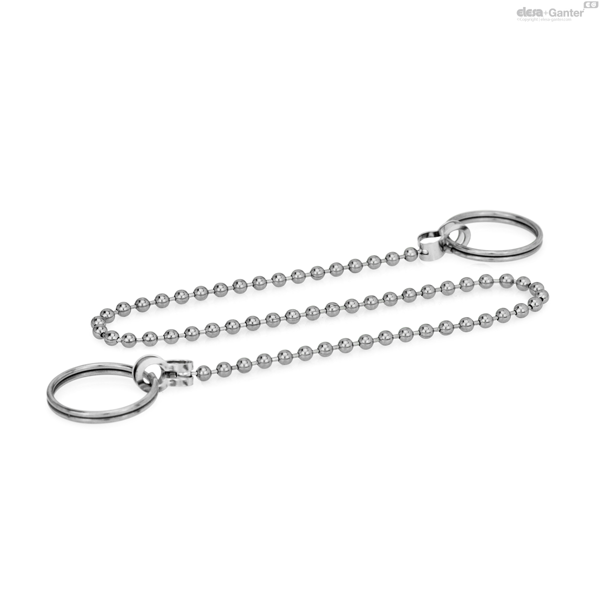
GN 111
Kogelkettingen
Messing, met twee sleutelringen
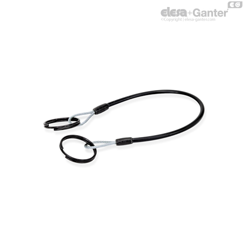
GN 111.2-A
Borgkabels
Roestvast staal, met sleutelringen of een sleutelring en een lus/met lussen of lipjes

GN 111.4
Spiraalvormige bevestigingskabels
Kunststof, met twee sleutelringen

GN 111.5
Kogelkettingen
Roestvrij staal, met twee sleutelringen