 Technical datasheet
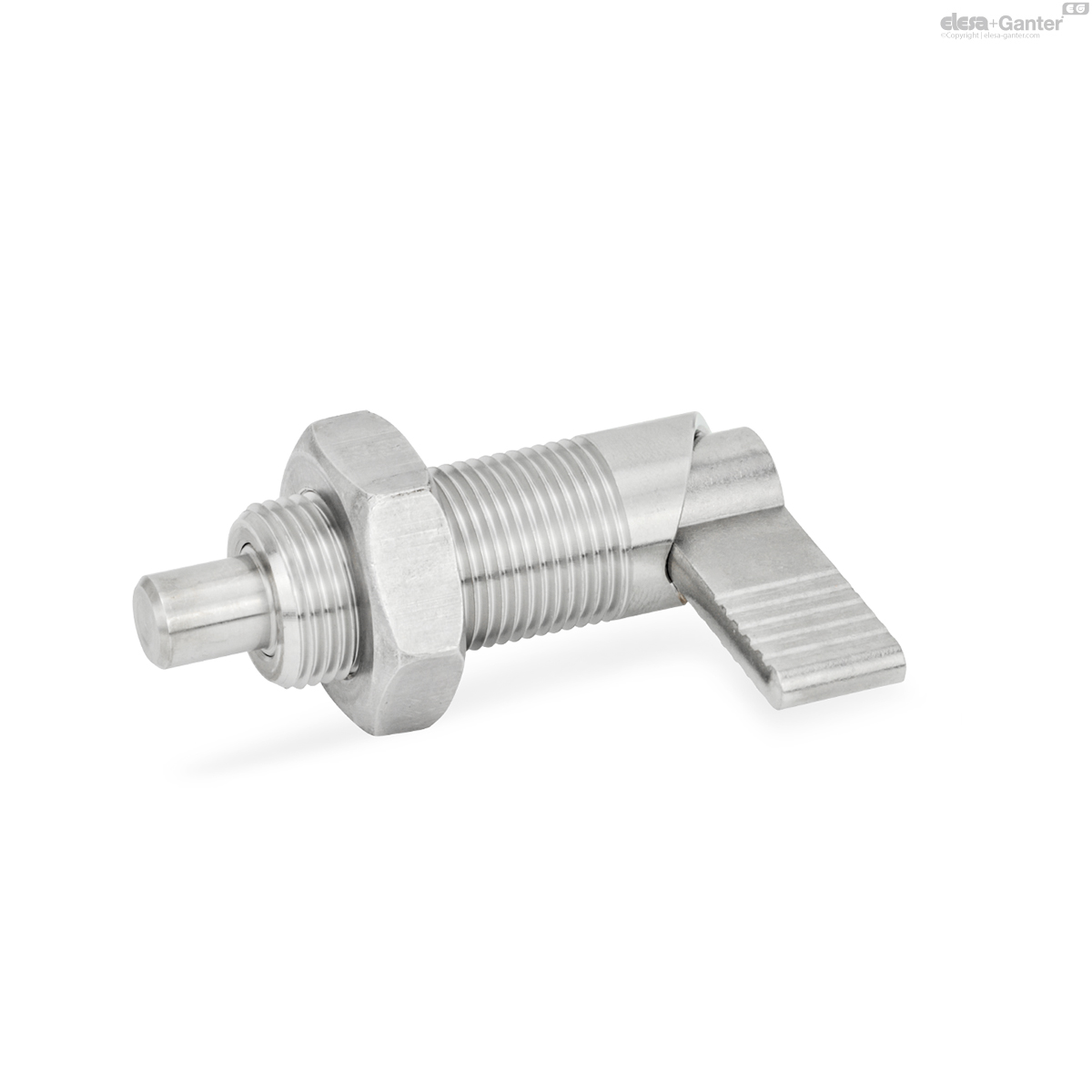
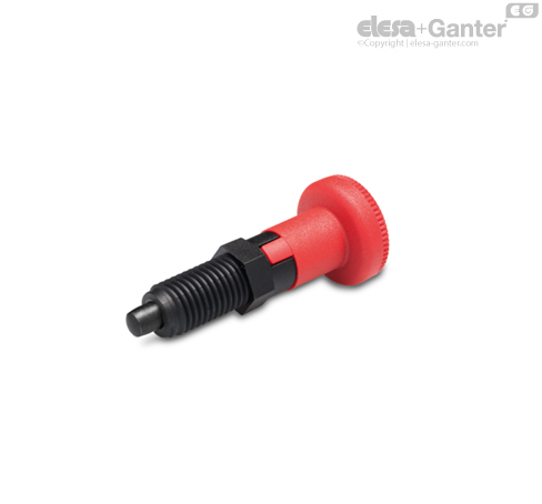
GN 612-NIDoigts d'indexage à came
Acier inoxydable
Acier / Acier inoxydable


GN 612-NI
|
Code
|
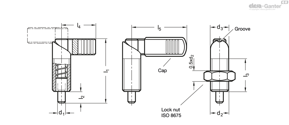
d1 Pin -0.05/-0.08
Bore H7 |
d2
|
d3
|
l1
|
l2
|
l3 +1.5
|
l4
|
l5
|
Spring load
in N ≈ initial |
Spring load
in N ≈ end |
|
|---|---|---|---|---|---|---|---|---|---|---|---|
|
|
|
|
|
|
|
|
|
|
|
|
|
|
GN 612-4-M10-AK-NI
|
4
|
M 10
|
10
|
37.5
|
6
|
19
|
21
|
-
|
7
|
20
|
22
|
|
GN 612-4-M10x1-AK-NI
|
4
|
M 10 x 1
|
10
|
37.5
|
6
|
19
|
21
|
-
|
7
|
20
|
22
|
|
GN 612-5-M10-AK-NI
|
5
|
M 10
|
10
|
37.5
|
6
|
19
|
21
|
-
|
7
|
20
|
22
|
|
GN 612-5-M10x1-AK-NI
|
5
|
M 10 x 1
|
10
|
37.5
|
6
|
19
|
21
|
-
|
7
|
20
|
23
|
|
GN 612-5-M12-AK-NI
|
5
|
M 12
|
12
|
47
|
8
|
26
|
26
|
32
|
8
|
18
|
35
|
|
GN 612-5-M12x1,5-AK-NI
|
5
|
M 12 x 1.5
|
12
|
47
|
8
|
26
|
26
|
32
|
8
|
18
|
37
|
|
GN 612-6-M10x1-AK-NI
|
6
|
M 10 x 1
|
10
|
37.5
|
6
|
19
|
21
|
-
|
7
|
20
|
23
|
|
GN 612-6-M10-AK-NI
|
6
|
M 10
|
10
|
37.5
|
6
|
19
|
21
|
-
|
7
|
20
|
22
|
|
GN 612-6-M12x1,5-AK-NI
|
6
|
M 12 x 1.5
|
12
|
47
|
8
|
26
|
26
|
32
|
8
|
18
|
40
|
|
GN 612-6-M12-AK-NI
|
6
|
M 12
|
12
|
47
|
8
|
26
|
26
|
32
|
8
|
18
|
35
|
|
GN 612-6-M16x1,5-AK-NI
|
6
|
M 16 x 1.5
|
16
|
56
|
10
|
30
|
32
|
42
|
11
|
29
|
79
|
|
GN 612-6-M16-AK-NI
|
6
|
M 16
|
16
|
56
|
10
|
30
|
32
|
42
|
11
|
29
|
75
|
|
GN 612-8-M12x1,5-AK-NI
|
8
|
M 12 x 1.5
|
12
|
47
|
8
|
26
|
26
|
32
|
8
|
18
|
40
|
|
GN 612-8-M12-AK-NI
|
8
|
M 12
|
12
|
47
|
8
|
26
|
26
|
32
|
8
|
18
|
38
|
|
GN 612-8-M16x1,5-AK-NI
|
8
|
M 16 x 1.5
|
16
|
56
|
10
|
30
|
32
|
42
|
11
|
29
|
78
|
|
GN 612-8-M16-AK-NI
|
8
|
M 16
|
16
|
56
|
10
|
30
|
32
|
42
|
11
|
29
|
82
|
|
GN 612-8-M20x1,5-AK-NI
|
8
|
M 20 x 1.5
|
20
|
69
|
12
|
36
|
37
|
52
|
21
|
57
|
153
|
|
GN 612-8-M20-AK-NI
|
8
|
M 20
|
20
|
69
|
12
|
36
|
37
|
52
|
21
|
57
|
119
|
|
GN 612-10-M16x1,5-AK-NI
|
10
|
M 16 x 1.5
|
16
|
56
|
10
|
30
|
32
|
42
|
11
|
29
|
80
|
|
GN 612-10-M16-AK-NI
|
10
|
M 16
|
16
|
56
|
10
|
30
|
32
|
42
|
11
|
29
|
78
|
|
GN 612-10-M20x1,5-AK-NI
|
10
|
M 20 x 1.5
|
20
|
69
|
12
|
36
|
37
|
52
|
21
|
57
|
150
|
|
GN 612-10-M20-AK-NI
|
10
|
M 20
|
20
|
69
|
12
|
36
|
37
|
52
|
21
|
57
|
151
|
|
GN 612-12-M20x1,5-AK-NI
|
12
|
M 20 x 1.5
|
20
|
69
|
12
|
36
|
37
|
52
|
21
|
57
|
160
|
|
GN 612-12-M20-AK-NI
|
12
|
M 20
|
20
|
69
|
12
|
36
|
37
|
52
|
21
|
57
|
153
|
Types
Types
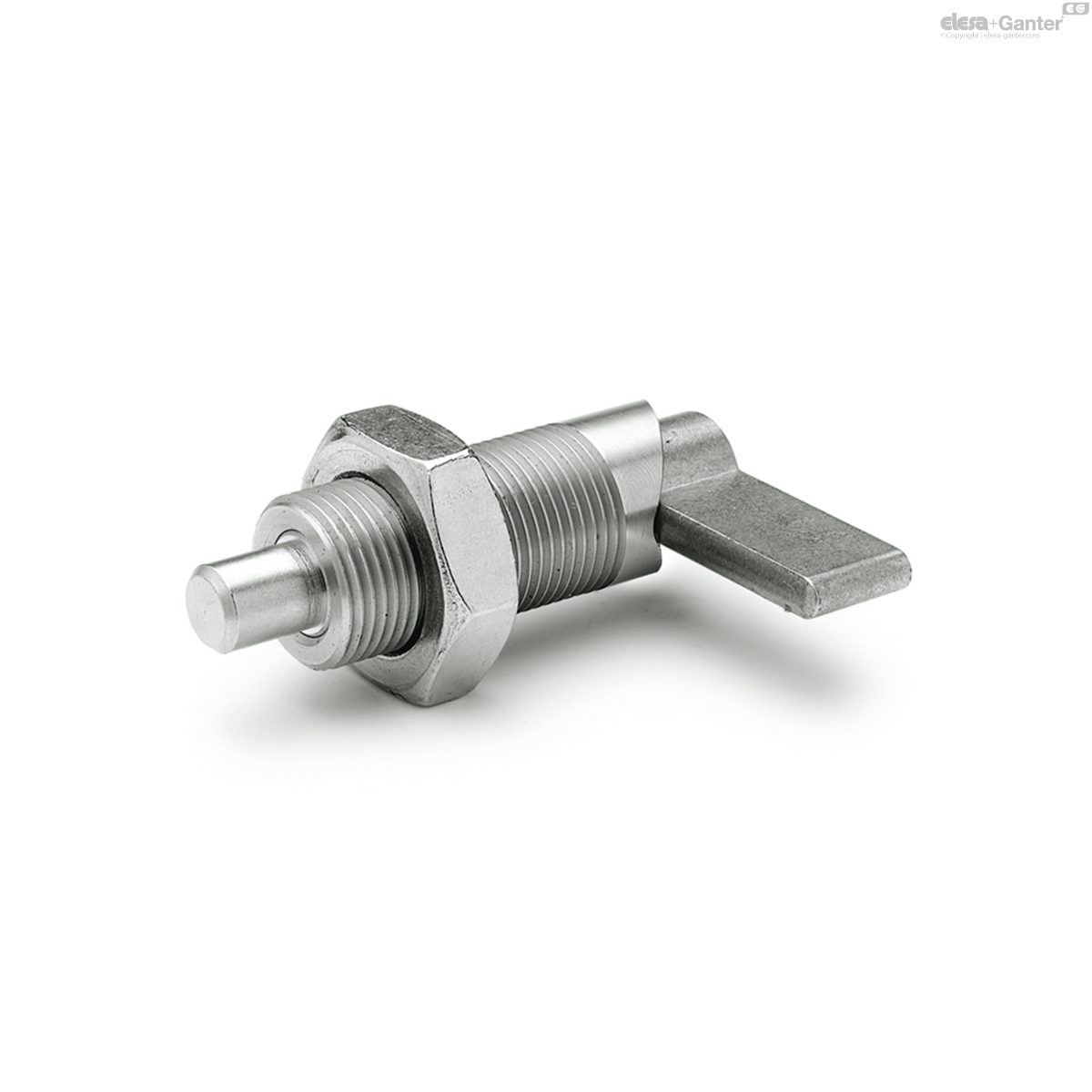
- Type A: Without plastic cap, without lock nut
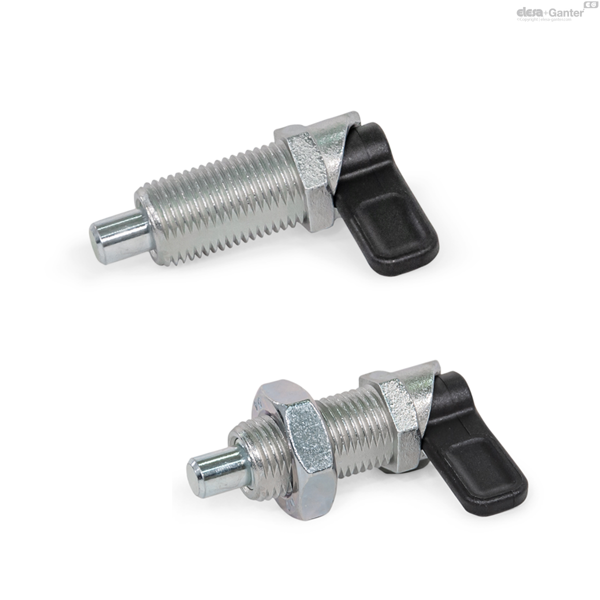
- Type B: With plastic cap, without lock nut
- Type AK: Without plastic cap, with lock nut
- Type BK: With plastic cap, with lock nut
Guide
Guide
- Steel, blackened
- Stainless steel AISI 303 NI
Plunger pin
Plunger pin
- Steel nitrided
- Stainless steel AISI 303 for NI
Latch arm
Latch arm
- Steel sintered
- Stainless steel AISI 316LHC sintered for NI
Cap for type B / BK
Cap for type B / BK
Plastic, polyamide (PA)
Black, matte finish
Pressure spring
Pressure spring
Stainless steel AISI 301
Cam action indexing plungers GN 612 are used in cases where the locking pin must not protrude all the time. By rotating the lock through 180° the locking pin withdraws itself. A groove is provided in either position to prevent the lock from rotating.
- GN 412.1 Mounting Blocks (Zinc Die Casting)
- GN 612.1 Mounting Blocks (Steel / Stainless Steel)
- GN 412.2 Positioning Bushings (with Collar)
- GN 412.4 Positioning Bushings (with Collar)
- GN 412.3 Positioning Bushings (with Ramping Cone)
- GN 412.5 Positioning Bushings (with Ramping Cone)
- GN 909 Thin Hex Nuts (Fine Thread)
- GN 909.5 Thin Hex Nuts (Fine Thread)
- ISO 4035 Thin Hex Nuts (Standard Thread)
- ISO 8675 Thin Hex Nuts (Fine Thread)
Produits associés

GN 612.1
Support pour doigt d'indexage
Acier / Acier inoxydable , pour doigts d'indexation / doigts d'indexation à came
GN 612.8
Doigts d'indexage à came
Corps fileté en zinc moulé sous pression

GN 909.5
Écrous plats à 6 pans
Acier inoxydable , pour pistons d'indexation / pistons d'indexation à action à came

PMT.100-A
Doigts d'indexation
Corps en SUPER-technopolymère
PMT.101-A
Doigts d'indexation
Position repos, Corps en SUPER-technopolymère

PMT.110-A
Doigts d'indexation
Corps en SUPER-technopolymère

PMT.200-A
Doigts d'indexation
Position repos, Corps en SUPER-technopolymère