Technical
datasheet
Technical
datasheet
Steel / Stainless Steel, for Welding


|
Catalogue
|
d1 Pin -0.05/-0.25
Bore +0.1/+0.3 |
d1 Pin -0.05/-0.25
Bore +0.2/+0.4 |
d2
|
s
|
l1 ≈
|
l2
|
l3
|
l4
|
A/F
|
Spring load
in N≈ initial |
Spring load
in N≈ end |
|
|---|---|---|---|---|---|---|---|---|---|---|---|---|
|
|
|
|
|
|
|
|
|
|
|
|
|
|
|
GN 722.1-8-20-A-ST
|
8
|
-
|
-
|
20
|
54
|
14
|
35
|
37
|
2.5
|
14
|
35
|
135
|
|
GN 722.1-10-20-A-ST
|
10
|
-
|
-
|
20
|
54
|
14
|
35
|
37
|
2.5
|
14
|
35
|
144
|
|
GN 722.1-12-20-A-ST
|
12
|
-
|
-
|
20
|
54
|
14
|
35
|
37
|
2.5
|
14
|
35
|
148
|
|
GN 722.1-14-20-A-ST
|
14
|
-
|
-
|
20
|
54
|
14
|
35
|
37
|
2.5
|
14
|
35
|
153
|
|
GN 722.1-16-30-A-ST
|
16
|
-
|
-
|
30
|
83
|
20
|
54
|
55
|
4
|
22
|
70
|
622
|
|
GN 722.1-20-30-A-ST
|
20
|
-
|
-
|
30
|
83
|
20
|
54
|
55
|
4
|
22
|
70
|
639
|
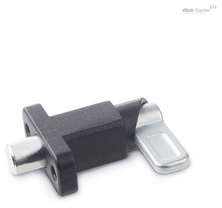
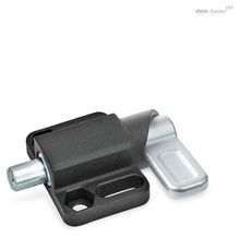
Guide
Weldable
Blackened
Weldable
Latch
Zinc plated, blue passivated (for ST)
Plunger pin
Stainless steel AISI 316 (for A4)
Pressure spring
Stainless steel AISI 316Ti
Countersunk screw
With spring latches GN 722.1, the plunger pin is retracted over the curve of the guide by a 180° turn of the latch. The notch at the upper end of the curve causes the latch to be held in place if the plunger pin needs to be kept temporarily from protruding. The ST version is designed for applications in steel construction, whereas the stainless steel version A4 is suitable for use in particularly aggressive environments.
The dimensional tolerances between plunger pin and guide are selected so that the functional reliability is guaranteed even after welding, applying a corrosion protection layer or in case of contamination.
For fastening by welding, the unmounted type AU is particularly recommended to avoid changes to the microstructure of the material due to heating of the spring and plunger pin. In this case, the indexing plunger is assembled only after the surface treatment of the welded guide.