Technical
datasheet
Technical
datasheet
with stepless positioning

|
Catalogue
|
d1
|
d2 H7
|
d3
|
d4 -0.2
|
d5
|
l1
|
l2
|
l3
|
|
|---|---|---|---|---|---|---|---|---|---|
|
|
|
|
|
|
|
|
|
|
|
|
GN 700-66-K12-A
|
66
|
K 12
|
52
|
55
|
5.5
|
44
|
9
|
40
|
600
|
|
GN 700-66-K14-A
|
66
|
K 14
|
52
|
55
|
5.5
|
44
|
9
|
40
|
540
|
|
GN 700-66-K12-B
|
66
|
K 12
|
52
|
55
|
5.5
|
44
|
9
|
40
|
580
|
|
GN 700-66-K14-B
|
66
|
K 14
|
52
|
55
|
5.5
|
44
|
9
|
40
|
560
|
|
GN 700-66-K12-S
|
66
|
K 12
|
52
|
55
|
5.5
|
44
|
9
|
40
|
580
|
|
GN 700-66-K14-S
|
66
|
K 14
|
52
|
55
|
5.5
|
44
|
9
|
40
|
560
|
|
GN 700-66-K12-KS
|
66
|
K 12
|
52
|
55
|
5.5
|
44
|
9
|
40
|
580
|
|
GN 700-66-K14-KS
|
66
|
K 14
|
52
|
55
|
5.5
|
44
|
9
|
40
|
560
|
Attachment part and bush
Steel
Blackened
Blocking mechanism
Steel
Hardened and ground
Scale ring and rotating knob
Aluminium
Black anodized
Scale / arrow
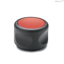
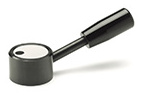
With this adjustable knob GN 700 a shaft can be infinitely adjusted in both directions. The anti-backlash mechanism with a max. load of 15 Nm ensures the firm locking of the shaft in any position.
This mechanism prevents any uncontrolled movement of the shaft. The locking action is a safety feature to prevent unwanted re-adjustments caused by backlash and vibration.
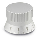
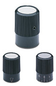
Scale and arrow on the control knobs are indelibly marked and easily legible.
Besides the standard scale (Type AS) the control knob version may be supplied with any other scale (Type KS).
Regarding design, numbering run, numbering position and numbering sequence of the scale please see the layout for scale rings on the order sheet 'How to order graduations' .
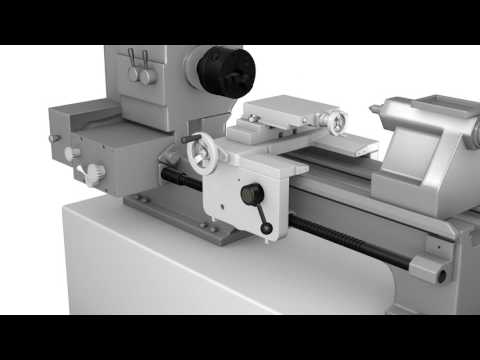
The anti-backlash mechanism which operates on the principle of a bidirectional freewheeling and antireversing basis allows the transfer of movement in both directions without backlash. The adjustable knob is not suitable for applications on machines or equipments which are exposed to vibrations.
The bush is connected by the key and keyway to the revolving shaft.
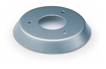
The location ring remains static and centrally positioned by the bushing and the two pinch rollers, fixed to the machine frame or housing by three screws.
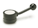
The rotating knob with the knurled barrel is carried by the bush.
The scale ring is firmly anchored to the bush and the driven shaft by two countersunk screws.
If the knob is repositioned, one of the follower pins – depending on the direction of rotation – pushes the pinch roller against the spring into an idling position which releases the bush and shaft to rotate freely.
The second follower pin on the opposite side reduces the movement of its pinch roller and ensures at the same time a firm grip and forward movement of the bush while the first pinch roller remains in an idling position.
When releasing the knob, the spring will push the pinch roller back into the grip position, thus linking the bush again with the static section.
The scale ring is connected firmly with the bush and any readjustment of the shaft can be accurately controlled.
This infinitely adjustable knob cannot, however, be used in such cases where the shaft to be adjusted runs ahead of the adjustment. The anti-backlash mechanism in this knob cannot be used as a bearing for the driven shaft.
A perfect functioning can only be guaranteed if the shaft of the machine is positioned at a perfect right angle to the contact surface of the static part.