Technical
datasheet
Technical
datasheet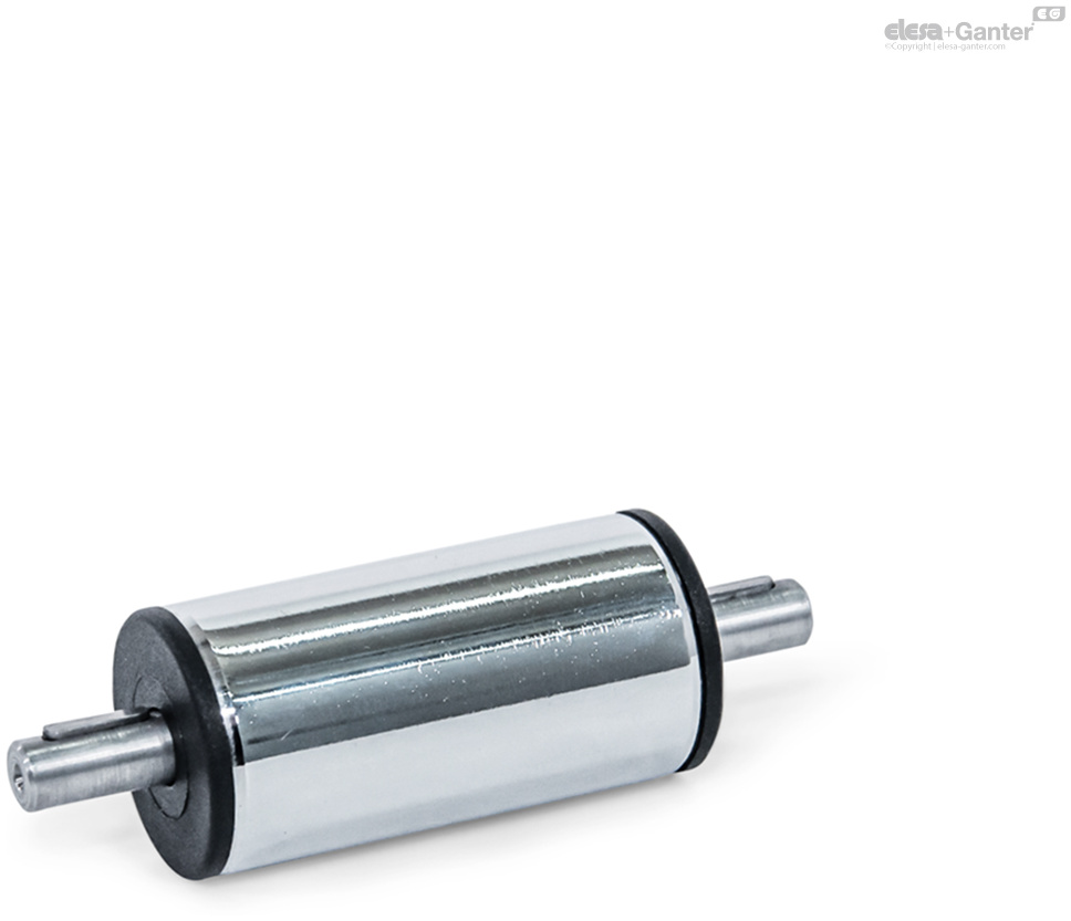
for the Connection of Linear Actuators
|
Catalogue
|
d1
|
l1
Standard lengths of the drive units |
Transfer units
|
d2
|
l2
|
|
|---|---|---|---|---|---|---|
|
|
|
|
|
|
|
|
|
GN 391-18-47-SCR
|
18
|
47
|
42 ... 500*
|
6
|
16
|
63
|
|
GN 391-30-60-SCR
|
30
|
60
|
55 ... 2000*
|
8
|
16
|
180
|
|
GN 391-40-93-SCR
|
40
|
93
|
88 ... 2500*
|
12
|
17
|
506
|
|
GN 391-50-93-SCR
|
50
|
93
|
88 ... 2500*
|
12
|
18
|
781
|
|
GN 391-60-95-SCR
|
60
|
95
|
90 ... 2800*
|
14
|
19
|
1165
|
Version in Steel
Guide tube
Tube DIN 2391
Steel, chrome-plated SCR
Version in Stainless Steel
Guide tube
Tube DIN 2462
Stainless steel AISI 304 NI
Shaft
Steel respectively stainless steel
Ball bearing
End cap
Plastic
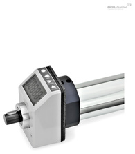
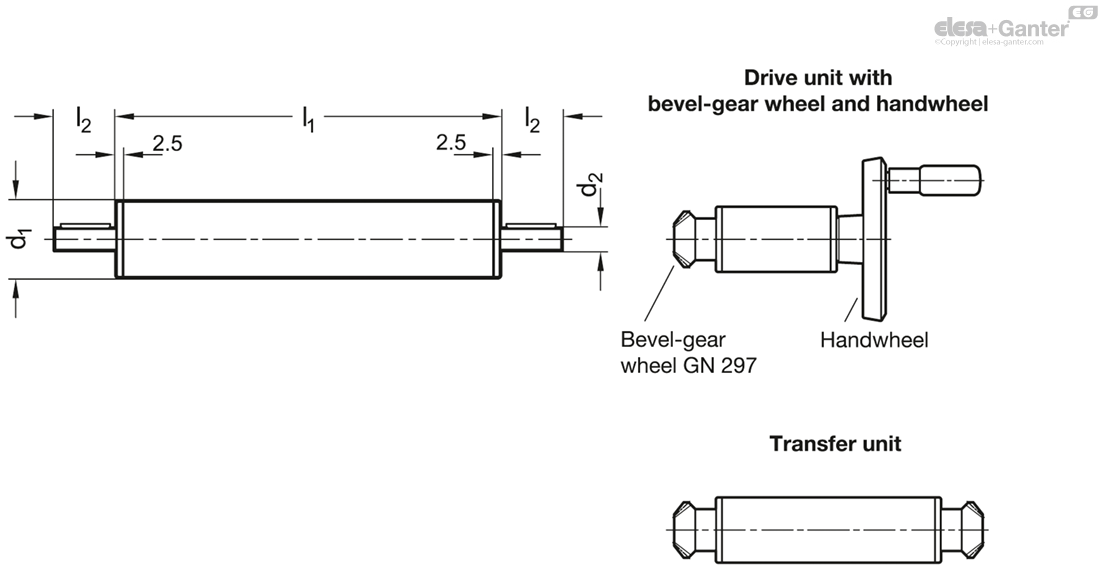
Transfer units GN 391 are normally used in connection with linear actuators. They are designed to transfer the rotary movement for operating the linear actuators to another or a further position.
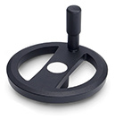
The transfer unit in the standard length l1 is a special design: It is designed to turn the operating axis for the linear actuators (handwheel) by 90° together with an angular gear.
As in linear actuators, digital position indicators can be fitted.
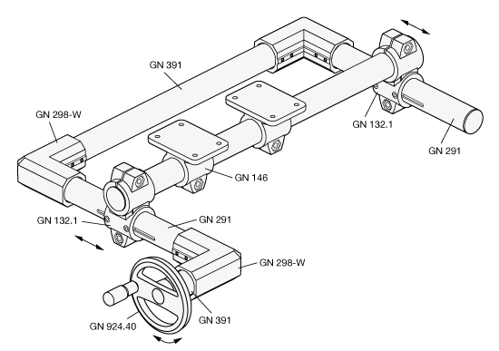
Two parallel sliding linear actuators GN 291 are connected with a transfer unit GN 391.
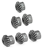
The angular housings GN 298-W including the bevel gear wheels GN 297 and another transfer unit GN 391 connect the handwheel with the system. The handwheel is placed in a rectangular position to the moving axes.
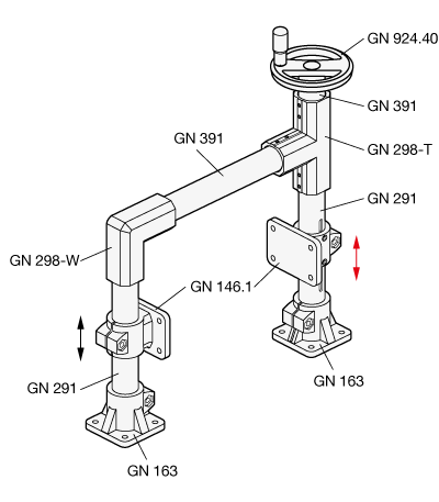
Two flanged linear actuator connectors GN 146.1 are moved parallel. For this two linear actuators GN 291 are connected with a transfer unit GN 391.
The T- and angular gear GN 298-T/-W including the bevel gear wheels GN 297 and another transfer unit GN 391 connect the handwheel with the system. The handwheel is placed in a parallel position to the moving axes.