Technical
datasheet
Technical
datasheet
Aluminium, fixed bearing flange

|
Catalogue
|
d1
|
d2 H7
|
b
|
l1
|
|
|---|---|---|---|---|---|
|
|
|
|
|
|
|
|
GN 327-160-K14-A-1
|
160
|
K 14
|
18
|
66
|
1706
|
|
GN 327-160-K14-A-2
|
160
|
K 14
|
18
|
66
|
1702
|
|
GN 327-160-K16-A-2
|
160
|
K 16
|
18
|
66
|
1686
|
|
GN 327-160-K16-A-1
|
160
|
K 16
|
18
|
66
|
1690
|
|
GN 327-160-K18-A-2
|
160
|
K 18
|
18
|
66
|
1666
|
|
GN 327-160-K18-A-1
|
160
|
K 18
|
18
|
66
|
1670
|
|
GN 327-160-K20-A-2
|
160
|
K 20
|
18
|
66
|
1645
|
|
GN 327-160-K20-A-1
|
160
|
K 20
|
18
|
66
|
1649
|
|
GN 327-200-K14-A-2
|
200
|
K 14
|
20.5
|
68
|
2043
|
|
GN 327-200-K14-A-1
|
200
|
K 14
|
20.5
|
68
|
2047
|
|
GN 327-200-K16-A-2
|
200
|
K 16
|
20.5
|
68
|
2027
|
|
GN 327-200-K16-A-1
|
200
|
K 16
|
20.5
|
68
|
2031
|
|
GN 327-200-K18-A-2
|
200
|
K 18
|
20.5
|
68
|
2007
|
|
GN 327-200-K18-A-1
|
200
|
K 18
|
20.5
|
68
|
2011
|
|
GN 327-200-K20-A-2
|
200
|
K 20
|
20.5
|
68
|
2000
|
|
GN 327-200-K20-A-1
|
200
|
K 20
|
20.5
|
68
|
1990
|
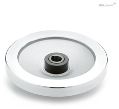
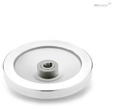
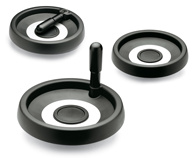
Handwheel body
Aluminium
Rim turned and polished
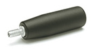
Coupling elements
Cylindrical Revolving handles GN 598
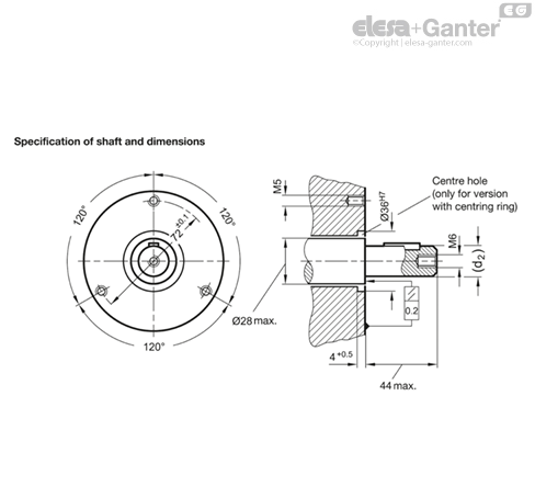
Safety handwheels GN 327 feature the ultimate in health and safety at work standards because the handwheel, if disengaged, is mounted on a fixed component, the bearing flange. The wheel is fully disengaged from the rotating shaft.
The bearing flange can also accept the bearing of the shaft via the bearing bushing (code No. 1). This bearing bushing is a dry bearing (DU bushing). Normally, the shaft has a separate bearing and the bearing bushing serves to center the bearing flange.
Centering can also be effected by a centering ring (code No. 2) if the appropriate bore hole has been made at the machine side. In this case there is no need for the bearing bushes and no bearing friction (heating) will occur.
Shaft bush and countershaft pulley are delivered in two separate components. Before assembly, make sure that the shaft bush can be pushed smoothly and free-moving over the shaft.
Proper function is guaranteed only if:
- shaft bush and bearing surface are level with each other
- the shaft axis lies at a right angle to the bearing surface on the machine side.
Design with bearing bush (Mode 1)
Push the handwheel and the shaft bush at the same time over the shaft, bolt down the bearing flange, and fix the shaft bush axially with the countershaft pulley
Design with centring ring (Mode 2)
The handwheel can be bolted at once through the centring ring above the bearing flange. Then push the shaft bush onto the shaft and fix it axially with the countershaft pulley.