Technical
datasheet
Technical
datasheet
Steel / Stainless Steel, with Right or Left Hand Thread


|
Catalogue
|
d1
|
l1
|
Max. stroke every
|
Threaded
spindle |
d2
|
d3
|
l2 Total length
|
l3
|
l4
|
m1
|
m2
|
For parallel key DIN 6885
|
|---|---|---|---|---|---|---|---|---|---|---|---|---|
|
|
|
|
|
|
|
|
|
|
|
|
|
|
|
GN 291-18-65-L1-SCR
|
18
|
65
|
350
|
TR10x3
|
6
|
M 3
|
l1+140
|
70
|
16
|
17
|
24
|
A2x2x12
|
|
GN 291-18-165-L1-SCR
|
18
|
165
|
350
|
TR10x3
|
6
|
M 3
|
l1+140
|
70
|
16
|
17
|
24
|
A2x2x12
|
|
GN 291-18-265-L1-SCR
|
18
|
265
|
350
|
TR10x3
|
6
|
M 3
|
l1+140
|
70
|
16
|
17
|
24
|
A2x2x12
|
|
GN 291-30-100-L1-SCR
|
30
|
100
|
1250
|
TR14x4
|
8
|
M 4
|
l1+205
|
102.5
|
16
|
23
|
38
|
A2x2x12
|
|
GN 291-30-150-L1-SCR
|
30
|
150
|
1250
|
TR14x4
|
8
|
M 4
|
l1+205
|
102.5
|
16
|
23
|
38
|
A2x2x12
|
|
GN 291-30-200-L1-SCR
|
30
|
200
|
1250
|
TR14x4
|
8
|
M 4
|
l1+205
|
102.5
|
16
|
23
|
38
|
A2x2x12
|
|
GN 291-30-300-L1-SCR
|
30
|
300
|
1250
|
TR14x4
|
8
|
M 4
|
l1+205
|
102.5
|
16
|
23
|
38
|
A2x2x12
|
|
GN 291-40-70-L1-SCR
|
40
|
70
|
1570
|
TR20x4
|
12
|
M 5
|
l1+235
|
117.5
|
17
|
42
|
54
|
A4x4x12
|
|
GN 291-40-170-L1-SCR
|
40
|
170
|
1570
|
TR20x4
|
12
|
M 5
|
l1+235
|
117.5
|
17
|
42
|
54
|
A4x4x12
|
|
GN 291-40-220-L1-SCR
|
40
|
220
|
1570
|
TR20x4
|
12
|
M 5
|
l1+235
|
117.5
|
17
|
42
|
54
|
A4x4x12
|
|
GN 291-40-270-L1-SCR
|
40
|
270
|
1570
|
TR20x4
|
12
|
M 5
|
l1+235
|
117.5
|
17
|
42
|
54
|
A4x4x12
|
|
GN 291-40-320-L1-SCR
|
40
|
320
|
1570
|
TR20x4
|
12
|
M 5
|
l1+235
|
117.5
|
17
|
42
|
54
|
A4x4x12
|
|
GN 291-50-65-L1-SCR
|
50
|
65
|
1565
|
TR20x4
|
12
|
M 6
|
l1+240
|
120
|
18
|
42
|
54
|
A4x4x12
|
|
GN 291-50-115-L1-SCR
|
50
|
115
|
1565
|
TR20x4
|
12
|
M 6
|
l1+240
|
120
|
18
|
42
|
54
|
A4x4x12
|
|
GN 291-50-215-L1-SCR
|
50
|
215
|
1565
|
TR20x4
|
12
|
M 6
|
l1+240
|
120
|
18
|
42
|
54
|
A4x4x12
|
|
GN 291-50-265-L1-SCR
|
50
|
265
|
1565
|
TR20x4
|
12
|
M 6
|
l1+240
|
120
|
18
|
42
|
54
|
A4x4x12
|
|
GN 291-50-315-L1-SCR
|
50
|
315
|
1565
|
TR20x4
|
12
|
M 6
|
l1+240
|
120
|
18
|
42
|
54
|
A4x4x12
|
|
GN 291-60-220-L1-SCR
|
60
|
220
|
1520
|
TR24x5
|
14
|
M 8
|
l1+285
|
142.5
|
19
|
58
|
70
|
A5x5x16
|
|
GN 291-60-720-L1-SCR
|
60
|
720
|
1520
|
TR24x5
|
14
|
M 8
|
l1+285
|
142.5
|
19
|
58
|
70
|
A5x5x16
|
* usually not available from stock
Guide tube
Tube DIN 2391
Steel, chrome-plated SCR
Tube DIN 2462
Stainless Steel AISI 304 NI
* usually not available from stock
Spindle with trapezoidal thread
Stainless steel AISI 303
Lead nut
Gunmetal
End plug
Plastic
In addition to the standard stroke lengths specified in the above table for linear actuators GN 291 any stroke inside the maximum stroke length is available.
Besides the extensive range of tube clamp connectors there are a number of different components for fixing the linear actuators and to build linear actuator connectors.
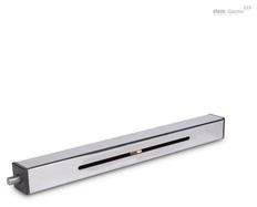
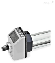
In order to measure the displacement and positioning of the linear actuator connectors, digital as well as analogue position indicators can be installed and furthermore the guide tube can be provided with a longitudinal scale.
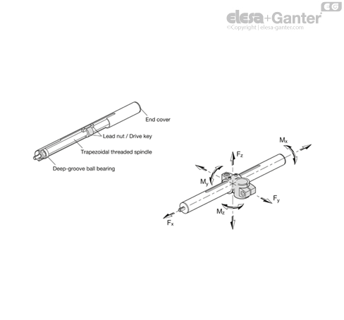
| Ø Linear actuator | Fx in N | Fy in N | - | - | Fz in N | - | - | Mx in Nm | My in Nm | Mz in Nm |
| l = 500 | l = 1000 | l = 1500 | l = 500 | l = 1000 | l = 1500 | - | - | - | ||
| 18 | 400 | 80 | - | - | 65 | - | - | 1.5 | 4.5 | 4.5 |
| 30 | 850 | 500 | 70 | 15 | 550 | 55 | 10 | 6.5 | 15 | 15 |
| 40 | 1100 | 2150 | 250 | 65 | 1900 | 150 | 50 | 15 | 42 | 42 |
| 50 | 1750 | 3100 | 650 | 150 | 3100 | 650 | 150 | 29 | 69 | 69 |
| 60 | 2600 | 4550 | 1500 | 400 | 4550 | 1400 | 350 | 45 | 125 | 125 |
The load data are applicable to linear actuators GN 291, GN 292 GN 293 made of Steel (SCR) or Stainless Steel (NI). The specified forces Fy and Fz cause a flexure of the guide tube of approx. 0.5mm.
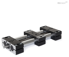
A lead nut moves in axial direction over the ball bearing trapezodial thread spindle of the linear actuator. The follower ensures the anti-rotation and makes the link to the different linear actuator connectors. The linear actuators have been designed for manual operation (handwheel).
The positioning accuracy is 0.2 mm / 300 mm stroke, the maximum reverse play is 0.1 mm.
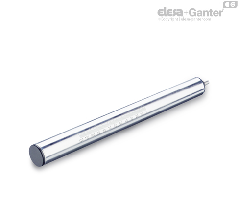
Guide tubes are available in chromed Steel (SCR) or stainless steel (NI) non-rusting. They made with the tolerance range of precision steel tubes DIN 2391 or DIN 2462.
A wide variety of different components are available in the tube clamp connector program to fix the linear actuators in place and to uprade these into linear actuator connectors.
Also, digital position indicators (DD52R / DD51) may be attached to measure the displacement or the positioning.
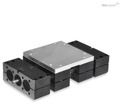
In applications where high torsion forces Mx occur, linear actuators with square tubing or double tube linear actuators should be given preference.
A wide variety of different components from the tube clamp connector program is also available for the square tubings. The linear actuator connectors are composed of two-part elements, with the effect that the precision of the square tubes involves no special requirements.
for Standard Stroke Lengths l1 of the Linear Actuators GN 291
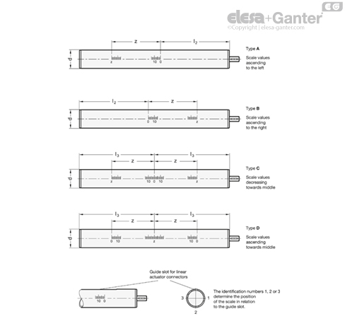
| Ø Linear actuator | l1 | l2 | l3 | z |
| Stroke | ||||
| (Standard lengths) | Scale length respectively highest figure | |||
| 18 | 65 | 82.5 | 147.5 | 90 |
| 18 | 165 | 82.5 | 247.5 | 190 |
| 18 | 265 | 82.5 | 347.5 | 290 |
| 30 | 100 | 122.5 | 222.5 | 120 |
| 30 | 150 | 122.5 | 272.5 | 120 |
| 30 | 200 | 122.5 | 322.5 | 220 |
| 30 | 300 | 122.5 | 422.5 | 320 |
| 40 | 70 | 142.5 | 217.5 | 90 |
| 40 | 170 | 142.5 | 317.5 | 190 |
| 40 | 220 | 142.5 | 367.5 | 240 |
| 40 | 270 | 142.5 | 417.5 | 290 |
| 40 | 320 | 142.5 | 467.5 | 340 |
| 50 | 65 | 147.5 | 217.5 | 90 |
| 50 | 115 | 147.5 | 267.5 | 190 |
| 50 | 215 | 147.5 | 367.5 | 240 |
| 50 | 265 | 147.5 | 417.5 | 290 |
| 50 | 315 | 147.5 | 467.5 | 340 |
| 60 | 220 | 182.5 | 402.5 | 240 |
| 60 | 720 | 182.5 | 902.5 | 740 |
Scale engraved with laser precision
The longitudinal scales GN 299 of type A and B are normally used in connection with the linear actuators Linear Actuators and Square Linear Actuators GN 291.1, the scales of type C and D are normally used for the linear actuators Linear Actuators GN 292 and Linear Actuators GN 293.
Longitudinal scales can only be ordered together with linear actuators.