Technical
datasheet
Technical
datasheet
for spring plungers

|
Catalogue
|
d1 p6
|
d2
|
d3 Ball-Ø spring plunger
|
l1 ±0.05
|
l2
|
s≈ for
GN 615 GN 615.2 GN 615.3 GN 615.5 GN 815 GN 815.1 |
s≈ for
GN 615.8 GN 615.9 |
s≈ for
GN 614 GN 614.2 GN 614.5 |
s≈ for
GN 614.3 |
s≈ for
GN 614.8 |
s≈ for
GN 615.1 GN 615.4 |
s≈ for
GN 616 GN 616.1 |
|---|---|---|---|---|---|---|---|---|---|---|---|---|
|
|
|
|
|
|
|
|
|
|
|
|
|
|
|
GN 249.1-4-1,8
|
4
|
1.8
|
*
|
5
|
1.5
|
M 4=0.4
|
M 6=0.4
|
Ø 3=0.4
|
Ø 3.5=0.4
|
Ø 5=0.4
|
M 5=0.4
|
M 5=0.4
|
|
GN 249.1-6-2,5
|
6
|
2.5
|
*
|
8
|
1.5
|
M 5=0.7 M 6=0.5
|
M 8=0.5
|
Ø 4=0.7 Ø 5=0.4
|
Ø 4=0.7 Ø 5=0.5
|
Ø 6=0.5
|
M 6=0.8 M 8=0.5
|
M 6=0.8 M 8=0.5
|
|
GN 249.1-8-3,5
|
8
|
3.5
|
*
|
10
|
2
|
M 8=0.8
|
M 10=0.8
|
Ø 6=0.7
|
Ø 6=0.8
|
Ø 8=1.5
|
M 10=0.8
|
M 10=1
|
|
GN 249.1-10-4,5
|
10
|
4.5
|
*
|
12
|
2
|
M 10=1
|
M 12=0.9
|
Ø 8=0.9
|
Ø 8=1
|
Ø 10=0.9
|
M 12=1
|
M 12=1
|
|
GN 249.1-12-6
|
12
|
6
|
*
|
14
|
2.5
|
M 12=1.4
|
M 16=1.2
|
Ø 10=1.4
|
Ø 10=1.4
|
Ø 12=1.2
|
M 16=1.2
|
M 16=1.5
|
|
GN 249.1-16-7,5
|
16
|
7.5
|
*
|
18
|
2.5
|
M 16=1.7
|
-
|
Ø 12=1.7
|
Ø 12=1.7
|
-
|
M 20=1.7
|
M 20=1.7
|
|
GN 249.1-20-8,5
|
20
|
8.5
|
*
|
22
|
3
|
M 20=1.8
|
-
|
-
|
-
|
-
|
M 24=1.6
|
-
|
Steel
hardened and ground
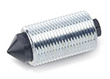
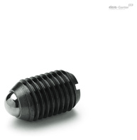
Ball buttons GN 249.1 are mainly used with spring plungers when low wear and exact positioning are needed.
To achieve optimal locking of the spring plungers, the maximum distance a between the ball button and the spring plunger should not be exceeded. The maximum distance a is calculated from the difference between the compression w of the selected plunger and the indentation depth s of the ball in the recess.
These ball buttons are especially recommended for use with spring plungers with high spring loads.