×
Login
NL
FR
EN
DE
Sign In
Create Account
Catalogue
Vacature
Catalog
Filter
New
Usually stock item
Group
Reset
39
Operating Elements
39
Clamping Knobs
46
Clamping Levers
76
U-Handles
24
Fixed and Revolving Handles
35
Control Elements
3
Rotary Controls
141
Indexing and Positioning Elements
159
Machine Elements
29
Joints
46
Levelling Elements
56
Hinges
41
Latches
89
Toggle Clamps
39
Accessories for Hydraulic Systems
94
Tube Clamp Connectors
Castors and Wheels
50
Magnets
7
Conveyor components
87
Linear motion components
10
Vibration-damping elements
29
Aluminum profiles
Vacuum components
1
Cable Ties
Gas springs
Vibration damper
Your query
Reset all
Query
EG_GN_134_7
Material
Reset
AlNiCo (AN)
8
Aluminium
246
BC_Aluminum
1
Brass
14
Cast iron
6
Die-cast zinc alloy
86
Duroplast
6
HD
1
Hard ferrite (HF)
12
NdFeB (ND)
35
Plastic
9
Plastic
12
Rubber - Stainless steel
10
Rubber - Steel
7
SmCo (SC)
10
Stainless steel
389
Stainless steel A4
14
Steel
394
TPU - Polyurethan (TPU)
1
Technopolymer
21
Technopolymer - Die-cast zin alloy
6
Technopolymer - Steel
4
Thermoplastic polyurethane (TPU)
1
Titanium
1
Handle
Reset
Fixed handle
3
Fold away handle
6
Revolving handle
21
Safety fold away handle
3
Without handle
20
Type of assembly
Reset
Blind hole
68
Blind holes
56
Blind holes - Threaded screws
3
For welding
6
Not drilled
5
Pass-through hole
29
Pass-through holes
52
Pass-through holes - Blind holes
2
Pass-through holes - Threaded screws
6
Plain hole
38
Plain hole and keyway
30
Square hole
9
Threaded screw
62
Threaded screws
15
Without holes
3
Threaded screw
Reset
M 3
2
M 4
2
M 5
2
M 6
26
M 8
42
M 10
41
M 12
38
M 14
3
M 16
32
M 20x1.5
2
M 20
24
M 24x2
2
M 24
19
M 30x2
2
M 30
5
M 36x2
2
M 42x2
2
Diameter
Reset
1-19
34
20-39
31
40-59
13
Threaded body
Reset
M6x0,75
1
M6
2
M8x0,75
2
M8
5
M8x1
8
M10
6
M10x1
15
M12
6
M12x1,5
23
M16
5
M16x1,5
25
M20x1,5
13
M24x2
2
Diameter
Reset
8
1
10
1
15
1
20
1
22
4
24
2
25
1
27
6
28
2
30
2
32
3
34
6
40
5
42
6
44
1
50
5
52
3
54
1
60
6
62
2
66
1
70
1
75
1
90
1
100
1
113
1
125
1
126
1
M6x1
2
M8x1
2
M10x1
2
Hole
Reset
6
1
7
1
8
4
10
14
11
1
12
32
14
30
15
1
16
21
17
4
18
23
19
2
20
20
22
13
24
4
26
4
Hole distance
Reset
18
2
19
1
22
1
25
6
27
1
30
9
33
1
34
3
36
12
37
1
40,8
4
45
2
48
1
50
1
50,8
1
52
1
55
5
60
1
64
1
65
1
66
1
71
2
76
1
80
1
96
1
Screw length
Reset
1-24
2
25-49
24
50-74
28
75-99
24
100-124
24
125-149
24
150-174
19
175-199
8
200-224
17
225-249
6
250-274
16
275-299
2
300-324
16
Hole
Reset
4.3
1
5.5
1
6.1
1
6.2
1
8.4
1
3.2
2
4.2
2
5.2
2
6.3
2
6.4
2
6.5
2
5.3
5
6.6
5
8.3
8
2
1
3
1
4
2
M 4
4
5
1
M 5
11
6
2
M 6
18
7
1
8
2
M 8
14
10
1
M 10
8
M 12
3
B 10
1
B 12
1
B 6
2
B 8
2
External diameter
Reset
50
1
63
1
80
3
100
6
125
22
140
21
160
24
200
23
250
14
315
1
400
1
Lever length
Reset
47.5
2
59.5
2
75.5
2
94.5
2
22
5
30
11
44
6
45
14
48
1
50
1
55
1
56
2
60
4
62
3
63
20
65
1
67
1
68
1
70
6
74
3
76
4
78
12
80
2
82
7
85
1
87
3
89
2
92
5
93
1
95
6
96
3
98
1
100
3
101
6
108
6
109
3
110
3
116
1
118
3
119
3
120
4
124
2
126
1
130
2
136
1
138
2
140
2
145
4
152
2
154
1
156
1
178
1
187
1
219
1
Tube dimension
Reset
M4
3
M5
4
6
4
M6
6
M8
3
8
7
10
2
M10
3
M12
1
12
10
14
5
15
2
16
2
18
3
20
2
30
3
40
3
50
3
60
3
B10
15
B10 | B10
2
B10 | B8
2
B12
27
B12 | B10
1
B12 | B12
2
B12 | B8
2
B14
16
B15
25
B15 | B10
2
B15 | B12
2
B15 | B15
2
B16
24
B16 | B10
1
B16 | B12
2
B16 | B15
1
B16 | B16
2
B18
25
B18 - B18
2
B20
53
B20 | B12
1
B20 | B15
2
B20 | B16
2
B20 | B20
2
B25
33
B30
53
B30 - B18
2
B30 - B30
2
B32
11
B35
11
B40
45
B40 - B40
2
B42
28
B45
29
B48
28
B50
44
B50 - B30
2
B50 - B50
2
B55
1
B60
8
B60 - B60
2
B8
10
B8 | B8
2
D10
5
D12
3
D14
2
D15
3
D16
3
D18
3
D20
4
D25
3
D30
3
D32
1
D35
2
D40
3
D42
1
D45
1
D48
1
D50
3
D55
1
D60
2
D8
3
G18
5
G18 - B18
1
G18 - G18
1
G30
12
G30 - B18
1
G30 - B30
1
G30 - G18
1
G30 - G30
1
G40
6
G40 - B40
1
G40 - G40
1
G50
10
G50 - B30
1
G50 - B50
1
G50 - G30
1
G50 - G50
1
G60
3
G60 - B60
1
G60 - G60
1
K12
1
K14
1
K6
1
K8
1
V10
4
V12
4
V14
1
V15
1
V16
4
V18
1
V20
13
V25
15
V30
20
V35
5
V40
21
V45
13
V50
20
V55
1
V60
1
V8
1
Hole centre distance
Reset
30
2
32
1
40
2
45
1
55
6
64
6
66
2
86
2
88
7
90
1
96
4
100
14
105
1
106
3
112
6
116
1
117
2
120
14
125
7
128
10
132
1
134
1
140
2
150
1
154
1
156
2
160
16
164
1
179
2
180
11
192
6
196
1
200
32
206
3
235
5
250
25
256
2
300
30
306
1
350
12
356
2
400
22
406
1
450
1
456
2
500
20
506
1
600
16
601
1
603
1
604
1
605
1
606
1
800
3
1000
2
movable
2
Housing material
Reset
Brass
2
Plastic
5
Rubber
1
Stainless steel
8
Steel
19
Steel with rubber jacket
8
External diameter
Reset
15
1
17
1
18
1
19
1
20
8
21
1
22
1
24
6
25
4
26
3
27
1
28
2
30
6
32
11
34
6
36
4
38
1
40
24
42
5
46
2
50
24
52
1
53
2
58
2
60
9
62
1
63
13
70
1
80
4
Threaded screw
Reset
M 3
5
M 4
15
M 5
21
M 6
33
M 8x1
1
M 8
45
M 10x1
2
M 10
39
M 12
23
M 16
11
M 20
1
Plunger diameter
Reset
3
1
4
13
5
19
6
37
7
6
8
40
10
27
12
11
14
2
16
4
20
2
Hole
Reset
3.6
1
4.5
1
6.5
1
8.4
1
8.5
1
4.3
2
5.4
2
5.3
3
5.5
3
6.4
5
M 3
10
M 4
24
5
7
M 5
35
M 6x1
1
6
12
M 6
73
7
1
M 8x1
2
8
17
M 8
91
M 10x1
2
10
20
M 10
63
12
15
M 12
44
M 14
5
14
7
16
8
M 16
23
18
1
20
3
M 20
10
22
1
28
1
B 10
10
B 12
9
B 14
2
B 16
6
B 20
1
B 4
2
B 5
4
B 6
5
B 8
8
K 10
1
K 12
1
K 16
1
SK 10
1
SK 14
1
SK 17
1
V 10
1
V 14
1
V 17
1
V 8
1
stainless-steel-boss
Reset
yes
2
Icon
Reset
1137
449
74
30
26
15
14
5
4
2
1
1
<<
«
1
2
3
4
5
6
7
8
9
10
»
>>
ALL
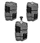
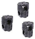
GN 134.7
Two-Way Locking Slide Units
Aluminum
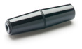
SI.134
Revolving handles
Duroplast
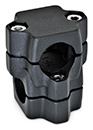
GN 134
Two-Way Connector Clamps
Aluminum, Multi Part Assembly
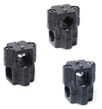
GN 134.1
Two-Way Linear Actuator Connectors
Aluminum, Multi Part Asssembly, for One-Axis system
GN 134.2
Two-Way Linear Actuator Connectors
Aluminum, Multi Part Assembly, for Two-Axis System
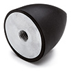
DVF.7
Rubber buffers
Silicone rubber and stainless steel
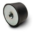
DVA.7
Rubber buffers
Rubber and steel or stainless steel
DVB.7
Rubber buffers
Rubber and steel or stainless steel
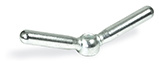
GN 99.7
Clamp nuts with double lever
Steel, zinc plated
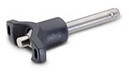
GN 113.7
Ball Lock Pins
Pin Stainless Steel AISI 303, with T-Handle
GN 798.7
Safety retractable handles
automatic return to the retracted position
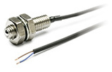
GN 615.7
Spring plungers
with limit switch
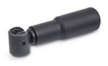
GN 614.7
Stainless Steel Spring Plungers
Press-Fit Type, Long Version, with Ball
GN 333.7
Tubular Handles
Stainless Steel
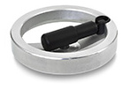
GN 322.7
Handwheels with retractable handle
Aluminium, Handle swivelling
GN 343.7
Levelling feet
Foot plastic / female thread Stainless Steel
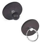
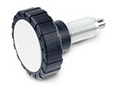
GN 51.7
Magnets
with Ball Knob / with Key Ring, with Rubber Jacket
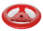
GN 227.7
Pressed steel handwheels
for valves
GN 709.7
Clamping pads
with female thread
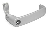
GN 115.7
Latches with cabinet 'U' handle
Operation with socket key
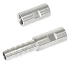
GN 480.7
Stainless Steel-Hose adapters
Barbed fitting / Thread
GN 7336.7
Clamping knobs with indexing plungers
GN 743.7
Oil level sight glasses
Brass / natural glass, resistant up to 100 °C
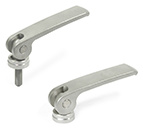
GN 927.7
Stainless Steel Clamping Levers with Eccentrical Cam
with Internal Thread / with Threaded Stud, Contact Plate Stainless Steel
<<
«
1
2
3
4
5
6
7
8
9
10
»
>>
ALL