Material
- Hinge body: self-extinguish high-rigidity SUPER-technopolymer, black or grey colour RAL 7040 (C33).
- Bosses: AISI 303 stainless steel, plain pass-through hole.
- Rotation pin: glass-fibre reinforced polyamide-based tecnopolymer (PA), black or grey colour RAL 7040 (C33).
- Assembly kit (see assembly instructions):
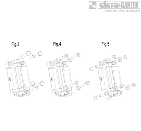
- n°4 technopolymer covers (fig.3).
- n°4 technopolymer bushings (fig.4 and fig.5).
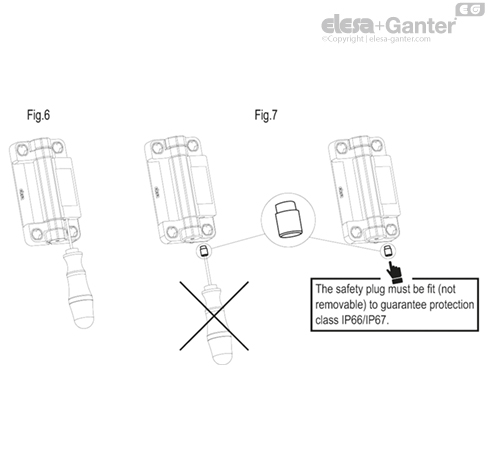
- n°2 thermoplastic elastomer safety plugs (fig.7) to guarantee IP67 protection class.
- Switch: four slow action electrical contacts with double interruption Zb shaped (see IEC EN 60947-5-1) wich can be set in normally open (NO) or normally closed (NC) mode in production.
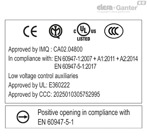
Positive opening in compliance with IEC EN 60947-5-1 annex K: the separation of the electrical contacts is the direct result of an actuator action on which an action force is applied by means of non elastic elements, that is to say not dependant on, for example, spring-like elements.
The contact elements guarantee a self-cleaning action of the silver-alloy pastes.
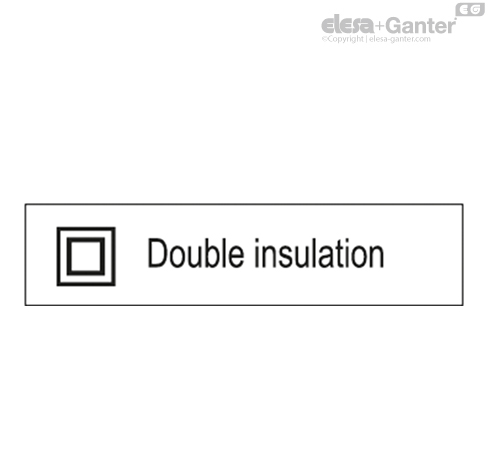
Thanks to its housing made out of SUPER-technopolymer, the CFSW hinge guarantees the double insulation of the internal circuits, therefore there is no need of grounding connection. Furthermore, the housing protects the electric contacts from shocks, atmospheric agents and accidental penetration of tools.
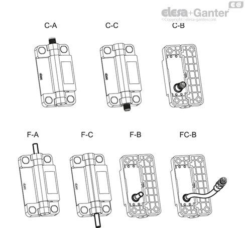
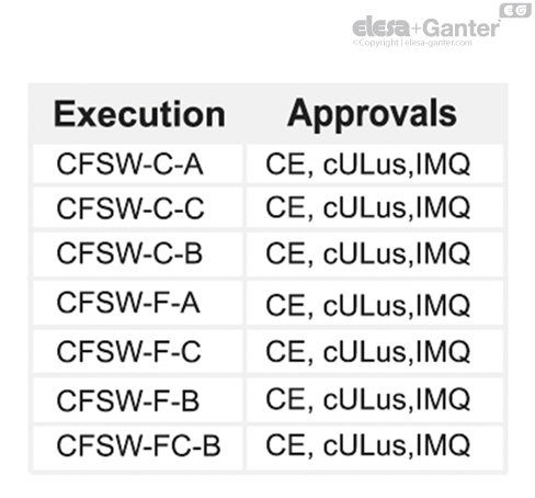
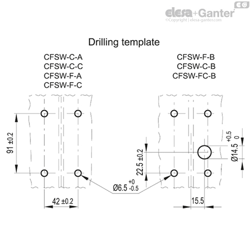
Standard executions
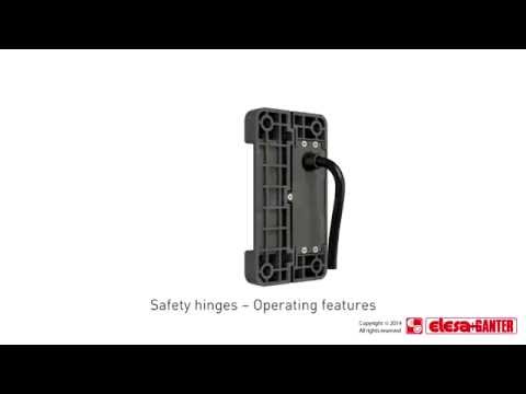
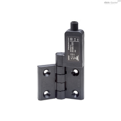
CFSW. hinge must be mounted with the side containing the microswitch on the fixed part (frame structure) and the other side on the movable part (door). The executions shown below refer to the hinges with the micro-switch on the right side.
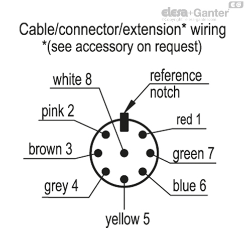
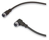
- C-A: 8 pole male connector, top axial output.
- C-C: 8 pole male connector, bottom axial output.
- C-B: 8 pole male connector, back output.
- F-A: 8 pole cable, length 2 or 5 metres, back axial output.
- F-C: 8 pole cable, length 2 or 5 metres, bottom axial output.
- F-B: 8 pole cable, length 2 or 5 metres, back output.
- FC-B: 0,2 m cable, with 8 pole male connector, back output.
Cable type: UL/CSA STYLE 2587 8 X AWG 22.
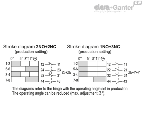
Contact blocks in the standard execution:
- NO-NC-NO-NC: 2 NO contacts + 2 NC contacts.
- NO-NC-NC-NC: 1 NO contact + 3 NC contacts.
Features and applications
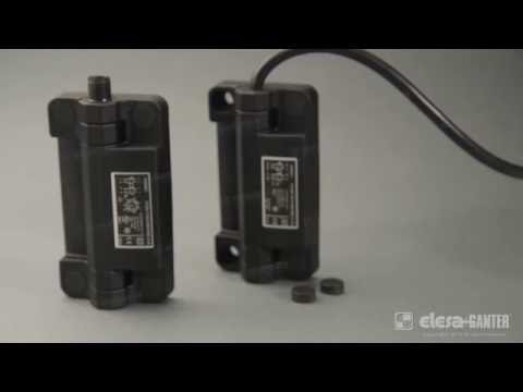
- Hinge with built-in multiple switch (ELESA patent) is a safety device because in case of accidental opening of doors, machine protections, or safety doors on machines and production equipment, it automatically breaks off the power supply hence protecting the operators.
- The hinge guarantees a level of IP66 protection against waves and powerful jets of water and IP67 protection against the effects of temporary immersion. It can be washed frequently and used in any environment where particular attention to cleanliness and hygiene is required, also thanks to the use of stainless steel parts for closing the hinge body. Correctly installed in laboratory tests, the hinge withstood high-pressure water jets such as those produced by a pressure washer.
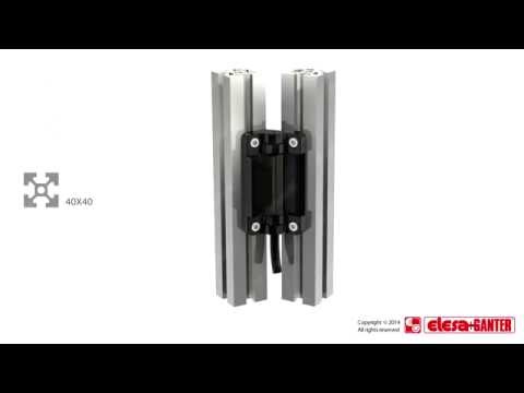
- Limited size, different assembly and output options (cable/connector) make this product easy to install on the most common aluminium profiles (30 mm minimum wide).
- Easy to assemble: the built-in safety multiple switch and the hinge come in one piece offering a very easy and fast assembly. This is a big advantage in comparison with some traditional systems which require to set up separately a hinge and a safety switch connected by a special pin to replace the standard pin of the hinge.
- Universal usage: CFSW. hinges can be assembled on the most common aluminium profiles.
- By using a redundant system, the CFSW hinges allow to have a system design up to SIL3 in compliance with IEC 62061, PLe in compliance with EN ISO 13849-1 or security category 4 in compliance with EN 954-1 with redundant structure.
- The maximum bending radius is 30 mm for the F executions with 8-pole cable, which can be used for fixed installation only.
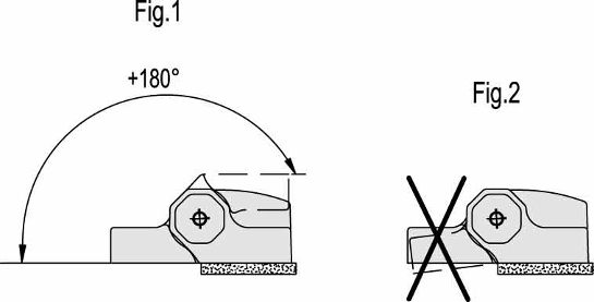
Rotation angle (approximate value)
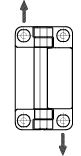
Max 180° (0° and +180° being 0° the condition where the two interconnected surfaces are on the same plane fig.1). The switching angle (see Built-in safety multiple switch functioning and maintenance) is guaranteed from this position. The condition where the two interconnected surfaces are on the same plane is to be strictly verified because the hinge must not be stressed by any negative angle (fig. 2).
| Resistance tests | AXIAL STRESS | RADIAL STRESS | 90° ANGLED STRESS |
 | 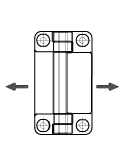 |  |
| Description | Max limit static load\rSa [N] | Max limit static load\rSr [N] | Max limit static load\rS90 [N] |
| CFSW.110 | 2100 | 2800 | 1300 |
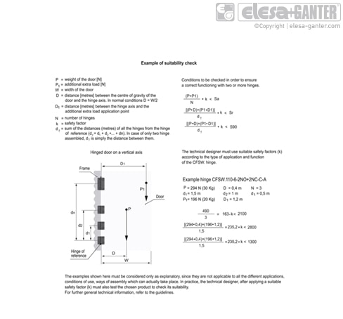
For CFSW. hinges with built-in safety multiple switch, the reference value supplied is the max limit static load (Sa, Sr, S90), since these hinges can be used as safety devices. Above this value, the material may break, thus prejudicing the hinge functionality. Obviously a suitable factor, according to the importance and safety level of the specific application, must be applied to this value. The load values shown in the tables of the different hinges are the result of tests carried out in our laboratories under controlled temperature and humidity (23°C-50% R.H.), under given conditions of use and for a limited period of time.
Built-in safety multiple switch functioning and maintenance
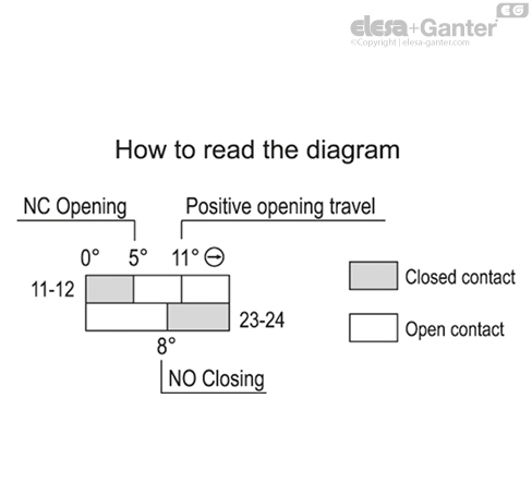
- The operating angle (see travel diagram) is set at 5° (we suggest to check it according to UNI EN ISO 13857).
- To guarantee the safety protection function, the hinge must be able to turn at least by 11° (see travel diagram), equivalent to the forced opening of the NC contacts by the actuator (positive opening).
- Before installing the hinge, the operating angle can be varied, in the case of particularly large doors, to reduce it to a minimum width of 2° (minimum value found in laboratory tests on specific equipment, under certain conditions of temperature, load, and humidity). The operation can be carried out with a Phillips screwdriver, by turning the adjustment screw clockwise (fig. 6).
The operation must be performed gradually by checking the opening angle of the door from time to time: in the case of excessive screw tightening, the NC contact may be open even with the door closed.In this case it will be necessary to loosen the screw by turning it anticlockwise until the hinge is functional again.Similarly, do not loosen the adjustment screw excessively, to prevent the head of the screw from hitting the hinge body by incorrectly positioning the actuator slider.Again, in this case it will be necessary to tighten the screw by turning it clockwise until the hinge is functional again.
After the adjustment is done, the safety plug must be fit (not removable) to guarantee protection class IP66/IP67 (fig.7).
The functioning points shown in the travel diagram undergo the same variation as the operating angle (ex: operating angle 2°, positive operating angle 8°).
Under normal conditions of use, when the mechanical life of the device is over, the operating angle can get to 3° from the starting angle.
We suggest to check prior to the start up and then periodically the proper functioning of the CFSW. hinge.
When the protection is opened the machine must immediately stop. When the protection is opened at any degrees, the machine must not be able to start.
Warnings
- The choice and use of CFSW. hinge is the responsibility of the customer who will check that the relevant application is compliant to the safety regulations in force in the actual operating conditions.
- Using CFSW. hinges always implies a full knowledge of and compliance with the safety regulations in force, including UNI EN ISO 13849-1, IEC EN 60204-1, UNI EN ISO 14119 and EN ISO 12100.
- The hinge must always be assembled and connected by qualified operators who have to check regularly the hinge perfect functioning.
- The hinge with built-in safety switch CFSW. must not be used in environments with frequent temperature changes which can cause condensation, in the presence of explosive or flammable gasses and must always be protected by a proper fuse (see Electrical features table).
- The structure of CFSW hinge must not be modified and the back cover has never to be removed: an improper installation or tampering of the hinge with built-in safety switch can make the protection ineffective and cause serious damages.
- During handling and storage the shown environmental conditions have to be observed.
Category of usage (values approved by IMQ) | | CFSW-C.. (connector) | CFSW-F.. (cable) |
AC15 standard| IEC 60947-5-1 Typical applications: electromagnetic load controls in alternating current | 24 V | - | 4 A |
| 120 V | - | 4 A |
| 250 V | - | 4 A |
| 400 V | - | 4 A |
DC13 standard IEC 60947-5-2 Typical applications: electromagnet controls in direct current | 24 V | 2 A | 2 A |
| 125 V | - | 0.4 A |
| 250 V | - | 0.3 A |
Remark: the category of usage AC 15 2A 24V may be applied to CFSW-C.., even though this category is not certified by IMQ, since it is not provided for the standards in use.
Mechanical features (values approved by IMQ) | Electrical features (values approved by IMQ) |
|---|
| Type of contacts: Ag 999 | Thermic power lth | Cable 4 A |
| Connector 2.5 A |
Maximum working frequence: 600 cycles/hour * | Short-circuit protection: 4A 500V gG |
Mechanical life-span (test carried in compliance with IEC EN 60947-5-1 regulation): 106 | Seal voltage at nominal pulse | Cable 4 Kv |
| Connector 2.5 Kv |
| Insulation nominal UI voltage | Cable: 400 Vac |
| Connector: 30 Vac/Vdc |
| Protection class of the housing EN60529: IP66/IP67 ** | Minimum force (torque for positive opening of contact): 0.5 Nm |
Speed of operation: minimum 2° / sec., maximum 90° / sec. | Short circuit conditioned current: 1000 A |
| Pollution degree: 3 |
| B10d = 2000000 |
| Tm = 20 years |
* A cycle of operations is equivalent to one closure and one opening as required by the standard EN60947-5-1.
** Fit the safety plug to guarantee IP66/IP67 protection (fig.7)
For CFSW-C..(connector) it is the customer's responsibility to check the protection class guaranteed by the connector of the cable used.
Category of usage (values approved by UL) | CFSW-F-A CFSW-F-C CFSW-F-B (cable) | CFSW-C-A CFSW-C-C CFSW-C-B (connector) |
|---|
C 300 AC control | 120 V | 1.5 A | Therm. current 2.5 A | 24 V / 2 A limited voltage-limited current / class 2 circuit |
| 240 V | 0.75 A |
Q 300 DC control | 125 V | 0.55 A | Therm. current 2.5 A |
| 250 V | 0.27 A |
Accessories on request
- FC.M12x1: extensions with 8 pole M12 female axial connector.
- PMW.: assembly plate on T-slot profiles.
- Assembly kit (code 426600 CFSW-KIT CALOTTE):
- n°4 technopolymer covers (fig.3).
- n°4 technopolymer bushings (fig.4 and fig.5).
- n°2 thermoplastic elastomer safety plugs (fig.7) to guarantee IP66/IP67 protection class.
Special executions on request
- Operating angle of the hinge other than from 0° to 180°, every 15°, where the system frame/door requires a special execution.
- NC and NO contact blocks setting (up to 4 NC).
- NO and NC ovelapping contacts.
Assembly Instructions
CFSW. hinge can be assembled in three different modes:
- With M6 UNI 5933 ISO 10642 countersunk-head screw (not supplied) and screw cover supplied in the kit (fig. 3) to avoid free access to screws.
- With cylindrical-head screw with hexagon socket M6 UNI 5931 ISO 4762 (not supplied) to set with the bushing supplied in the kit (fig.4).
- With M6 UNI 5588 ISO 4032 nut (not supplied) and the bushing supplied in the kit (fig.5). This kind of assembly makes the hinge totally tamper-proof preventing any tampering.
- Fit the hinge side with the built-in microswitch on the fixed part (the frame) and the other side on the door.
- Leave the least clearance between the holes in the mounting walls and the diameter of the setscrews (Max 0.5 mm). The suggested tightening torque should not be exceeded: 10 Nm.
- The hinge must not be used as a mechanical end-stroke either for door maximum opening or for closed door. For this purpose we recommend using external mechanical stops to prevent the door from opening completely against the hinge body assembled on the frame (fig.1) or exceeding the angle where the two interconnected surfaces are on the same plane (fig.2).
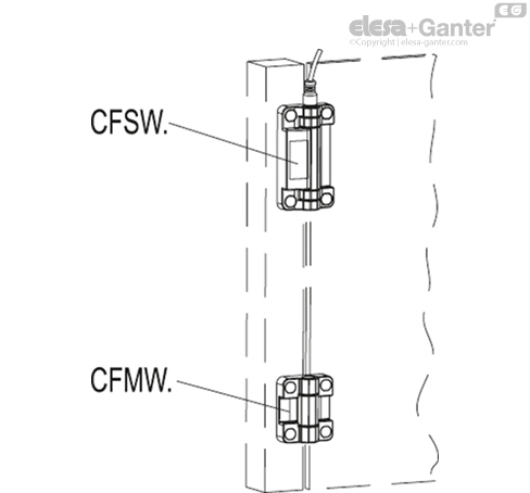
- CFSW. hinge is generally assembled with one or more complementary hinges CFMW. . In case of horizontal door opening or of a limited weight it is possible to use one hinge only.
- The connection cables must always be protected against mechanical damages.
Contacts and cables
The built-in safety switch is available with 4 contacts which can be set in production in the normally closed NC or normally open NO mode.
- NC contact with positive opening is mainly used for safety applications. The use of more than one NC switches reduces the risk of error of the single commutation.
- NO contact can be used simultaneously with the NC contact thanks to their electrical separation. The use of NO together with NC contacts guarantees a safety diversification.
- Cable with M12x1 connector following the shown circuit scheme.
 Technical
datasheet
Technical
datasheet