Technical
datasheet
Technical
datasheet
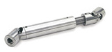
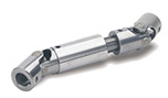
Steel / Stainless Steel, single or double

|
Catalogue
|
d1
|
t+1 max. assembly length
of the shaft |
d2 H7
|
s H10
|
l1
|
l2
|
l3
|
l4
|
|
|---|---|---|---|---|---|---|---|---|---|
|
|
|
|
|
|
|
|
|
|
|
|
DIN 808-16-B6-34-EG-NI
|
16
|
8
|
6
|
-
|
34
|
-
|
17
|
-
|
40
|
|
DIN 808-16-K6-34-EG-NI
|
16
|
8
|
6
|
-
|
34
|
-
|
17
|
-
|
38
|
|
DIN 808-16-V6-34-EG-NI
|
16
|
8
|
-
|
V 6*
|
34
|
-
|
17
|
-
|
40
|
|
DIN 808-16-B6-56-DG-NI
|
16
|
8
|
6
|
-
|
-
|
56
|
17
|
22
|
60
|
|
DIN 808-16-K6-56-DG-NI
|
16
|
8
|
6
|
-
|
-
|
56
|
17
|
22
|
65
|
|
DIN 808-16-V6-56-DG-NI
|
16
|
8
|
-
|
V 6*
|
-
|
56
|
17
|
22
|
60
|
|
DIN 808-16-B8-40-EG-NI
|
16
|
11
|
8
|
-
|
40
|
-
|
20
|
-
|
33
|
|
DIN 808-16-K8-40-EG-NI
|
16
|
11
|
8
|
-
|
40
|
-
|
20
|
-
|
40
|
|
DIN 808-16-V8-40-EG-NI
|
16
|
11
|
-
|
V 8*
|
40
|
-
|
20
|
-
|
40
|
|
DIN 808-16-B8-62-DG-NI
|
16
|
11
|
8
|
-
|
-
|
62
|
20
|
22
|
65
|
|
DIN 808-16-K8-62-DG-NI
|
16
|
11
|
8
|
-
|
-
|
62
|
20
|
22
|
65
|
|
DIN 808-16-V8-62-DG-NI
|
16
|
11
|
-
|
V 8*
|
-
|
62
|
20
|
22
|
64
|
|
DIN 808-22-B10-48-EG-NI
|
22
|
12
|
10
|
-
|
48
|
-
|
24
|
-
|
100
|
|
DIN 808-22-K10-48-EG-NI
|
22
|
12
|
10
|
-
|
48
|
-
|
24
|
-
|
97
|
|
DIN 808-22-V10-48-EG-NI
|
22
|
12
|
-
|
V 10*
|
48
|
-
|
24
|
-
|
90
|
|
DIN 808-22-B10-74-DG-NI
|
22
|
12
|
10
|
-
|
-
|
74
|
24
|
26
|
150
|
|
DIN 808-22-K10-74-DG-NI
|
22
|
12
|
10
|
-
|
-
|
74
|
24
|
26
|
144
|
|
DIN 808-22-V10-74-DG-NI
|
22
|
12
|
-
|
V 10*
|
-
|
74
|
24
|
26
|
145
|
|
DIN 808-25-B12-56-EG-NI
|
25
|
13
|
12
|
-
|
56
|
-
|
28
|
-
|
50
|
|
DIN 808-25-K12-56-EG-NI
|
25
|
13
|
12
|
-
|
56
|
-
|
28
|
-
|
146
|
|
DIN 808-25-V12-56-EG-NI
|
25
|
13
|
-
|
V 12*
|
56
|
-
|
28
|
-
|
140
|
|
DIN 808-25-B12-86-DG-NI
|
25
|
13
|
12
|
-
|
-
|
86
|
28
|
30
|
225
|
|
DIN 808-25-K12-86-DG-NI
|
25
|
13
|
12
|
-
|
-
|
86
|
28
|
30
|
219
|
|
DIN 808-25-V12-86-DG-NI
|
25
|
13
|
-
|
V 12*
|
-
|
86
|
28
|
30
|
219
|
|
DIN 808-32-B16-68-EG-NI
|
32
|
16
|
16
|
-
|
68
|
-
|
34
|
-
|
290
|
|
DIN 808-32-K16-68-EG-NI
|
32
|
16
|
16
|
-
|
68
|
-
|
34
|
-
|
289
|
|
DIN 808-32-V16-68-EG-NI
|
32
|
16
|
-
|
V 16*
|
68
|
-
|
34
|
-
|
274
|
|
DIN 808-32-B16-105-DG-NI
|
32
|
16
|
16
|
-
|
-
|
105
|
34
|
37
|
435
|
|
DIN 808-32-K16-105-DG-NI
|
32
|
16
|
16
|
-
|
-
|
105
|
34
|
37
|
427
|
|
DIN 808-32-V16-105-DG-NI
|
32
|
16
|
-
|
V 16*
|
-
|
105
|
34
|
37
|
427
|
|
DIN 808-42-B20-82-EG-NI
|
42
|
18
|
20
|
-
|
82
|
-
|
41
|
-
|
600
|
|
DIN 808-42-K20-82-EG-NI
|
42
|
18
|
20
|
-
|
82
|
-
|
41
|
-
|
600
|
|
DIN 808-42-V20-82-EG-NI
|
42
|
18
|
-
|
V 20*
|
82
|
-
|
41
|
-
|
570
|
|
DIN 808-42-B20-128-DG-NI
|
42
|
18
|
20
|
-
|
-
|
128
|
41
|
46
|
919
|
|
DIN 808-42-K20-128-DG-NI
|
42
|
18
|
20
|
-
|
-
|
128
|
41
|
46
|
900
|
|
DIN 808-42-V20-128-DG-NI
|
42
|
18
|
-
|
V 20*
|
-
|
128
|
41
|
46
|
886
|
|
DIN 808-50-B25-108-EG-NI
|
50
|
26
|
25
|
-
|
108
|
-
|
54
|
-
|
1130
|
|
DIN 808-50-K25-108-EG-NI
|
50
|
26
|
25
|
-
|
108
|
-
|
54
|
-
|
1098
|
|
DIN 808-50-V25-108-EG-NI
|
50
|
26
|
-
|
V 25*
|
108
|
-
|
54
|
-
|
1065
|
|
DIN 808-50-B25-163-DG-NI
|
50
|
26
|
25
|
-
|
-
|
163
|
54
|
55
|
1620
|
|
DIN 808-50-K25-163-DG-NI
|
50
|
26
|
25
|
-
|
-
|
163
|
54
|
55
|
1628
|
|
DIN 808-50-V25-163-DG-NI
|
50
|
26
|
-
|
V 25*
|
-
|
163
|
54
|
55
|
1585
|
Steel
blank
Joint bearing areas / pins / bearing sleeves
case hardened
Stainless Steel AISI 304 NI
Steel
blank
Joint bearing areas, pins
case hardened
The permissible r.p.m. of universal joints with friction bearing DIN 808 is to a large extent dependent on the type of application such as load, duration, angular disposition as well as lubrication. For over 1000 r.p.m. universal joints with needle bearing should be used
For continuous use ample lubrication is essential. This achieved by fitting the joint with a grease filled gaiter GN 808.1
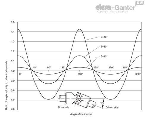
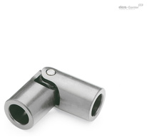
The single universal joints transfer the initial smooth rotation as an irregular rotation. One revolution of the drive shaft via single universal joint will cause the driven shaft to accelerate and decelerate twice. The extent of the irregularity depends on the operating angle ß.
In order to obtain a smooth rotation of the driven shaft two single or one double universal joint is required. In such cases where minor irregularities in the movement are acceptable or where minor operating angles are the norm a single universal joint will do.
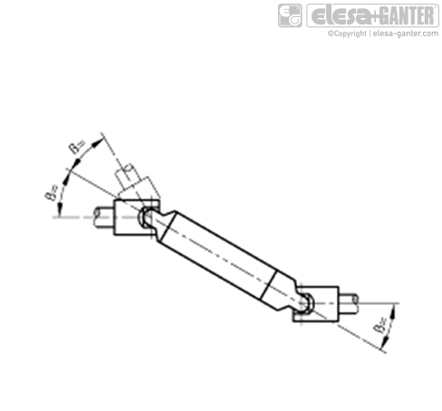
For a smooth transfer of a rotating speed, the angle of inclination ß must be equal at both ends of the connecting shaft.
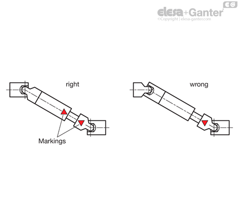
Due to a misconnection of the universal joint shafts, the irregular rotation of each joint is not compensated, but strengthened. This allows joint bearings and wedge profiles to be destroyed. For this reason, the markings of the universal joint shaft halves have to be opposite to each other.
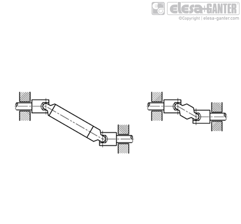
Furthermore the bearings must be as close as possible to the universal joints.
For continuous operation of universal joints with friction bearings adequate lubrication is essential. If drip lubrication is not possible they should be lubricated at least once a day. It is also possible to fit the universal joint with a gaiter GN 808.1 which can be filled with oil or grease.
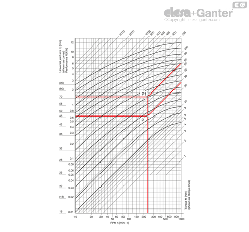
The table shows the transferable output N and/or torques M of universal joints DIN 808, type EG (single friction bearing) in relation
The values are only applicable to a constant speed of rotation, constant load and an operating inclination angle of max. 10°. They are not applicable to universal joints in Stainless Steel.
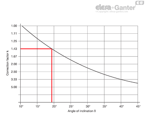
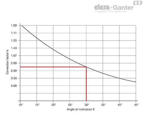
For larger inclination angles ß a nominal output N increased by the correction coefficient k and/or a nominal torque M has to be selected (see example below).
Conversion formular:
Torque M [Nm] = 9550 N[kW]/n [min-1]
Output N [kW] = M [Nm] x n [min-1]
1 kW = 1.36 PS / 1 PS = 0.736 kW
Example 1
Output to be transferred N = 0.65 kW
R.p.m. n = 230 min-1
Angle of inclination ß = 10°
Correction coefficient k = 1
Indicative output N‘= Nominal output N
Intersection point P results from 0.65 kW and 230 min-1 (which corresponds to a torque of 27 Nm).
The next size up universal joint corresponding to point P is the model with a diameter d1 = 25.
Example 2
Torque to be transferred M = 27 Nm
R.p.m. n = 230 min-1
Angle of inclination ß = 30°
Correction coefficient k = 2.25
Indicative torque = 2.25 x 27 Nm = 60 Nm
Intersection point P1 results from 61 Nm and 230 min-1 (which is equivalent to an indicative output N = 1.47 kW).
The next size up universal joint corresponding to P1 is the model with a diameter d1 = 36.
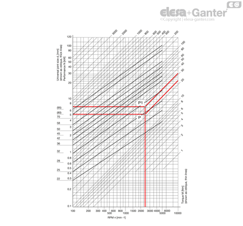
The table shows the transferable output N and/or torques M of universal joints DIN 808, type EW (single needle bearing) in relation
The values are only applicable to a constant speed of rotation, constant load and an operating inclination angle of max. 10°.
For larger inclination angles ß a nominal output N increased by the correction coefficient k and/or a nominal torque M has to be selected (see example below).
Conversion formular:
Torque M [Nm] = 9550 N[kW]/n [min-1]
Output N [kW] = M [Nm] x n [min-1]
1 kW = 1.36 PS / 1 PS = 0.736 kW
Example 1
Torque to be transferred N = 5.5 kW
R.p.m. n = 2300 min-1
Angle of inclination ß = 10°
Correction coefficient k = 1
Indicative output N‘= Nominal output N
Intersection point P results from 5.5 kW and 2300 min-1 (which corresponds to a torque of 23 Nm).
The next size up universal joint corresponding to point P is the model with a diameter d1 = 28.
Example 2
Torque to be transferred M = 23 Nm
R.p.m. n = 2300 min-1
Angle of inclination ß = 18°
Correction coefficient k = 1.43
Indicative torque = 1.43 x 23 Nm = 33 Nm
Intersection point P1 results from 33 Nm and 2300 min-1 (which is equivalent to an indicative output N = 7.9 kW).
The next size up universal joint corresponding to P1 is the model with a diameter d1 = 32.