×
Login
NL
FR
EN
DE
Sign In
Create Account
Catalogue
Vacature
Catalog
Filter
New
Usually stock item
Group
Reset
Operating Elements
Clamping Knobs
2
Clamping Levers
U-Handles
Fixed and Revolving Handles
6
Control Elements
Rotary Controls
4
Indexing and Positioning Elements
6
Machine Elements
2
Joints
6
Levelling Elements
10
Hinges
1
Latches
3
Toggle Clamps
1
Accessories for Hydraulic Systems
Tube Clamp Connectors
2
Castors and Wheels
Magnets
Conveyor components
2
Linear motion components
Vibration-damping elements
Aluminum profiles
Vacuum components
Cable Ties
Gas springs
Vibration damper
Your query
Reset all
Query
EG_CFM-TR-G
Material
Reset
Aluminium
6
Die-cast zinc alloy
2
Duroplast - Stainless steel
1
Duroplast - Steel
1
Stainless steel
9
Steel
14
Technopolymer
12
Technopolymer - Steel
2
Type of assembly
Reset
Blind hole
2
Blind holes
1
Pass-through holes
8
Pass-through holes - Threaded screws
1
Threaded screw
2
Threaded screws
1
Threaded screw
Reset
M 5
1
M 6
3
M 8
3
M 10
4
M 12
6
M 16
6
M 20
4
Diameter
Reset
1-19
1
20-39
1
Threaded body
Reset
M8x1
1
M10x1
3
M12x1,5
3
M16x1,5
3
M20x1,5
3
M24x2
1
Diameter
Reset
50
2
75
1
Hole distance
Reset
18
3
25
5
30
6
34
1
36
6
Screw length
Reset
25-49
2
50-74
2
75-99
2
100-124
2
125-149
2
Hole
Reset
5.5
2
6.5
2
4
2
5
4
6
6
8
3
Lever length
Reset
30
2
45
2
63
2
78
2
Tube dimension
Reset
V25
2
V30
2
V40
2
V50
2
Carrying capacity
Reset
0 - 1400 N
2
Bracket material
Reset
Steel
2
Threaded screw
Reset
M 3
1
M 4
1
M 5
1
M 6
1
M 8
1
M 10
1
Plunger diameter
Reset
4
1
5
4
6
4
8
4
10
3
12
1
16
1
Hole
Reset
M 3
1
M 4
2
M 5
2
M 6
2
M 8
2
M 10
2
Icon
Reset
45
15
10
9
6
1
1
1
1
<<
«
1
2
»
>>
ALL
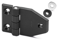
CFM-TR-G
Hinges for mounting on glass or panels
SUPER-Technopolymer
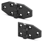
CFM-TR
Hinges
SUPER-Technopolymer
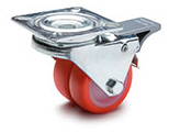
RE.C6-G
Twin castors for the general public with steel bracket
Injected polyurethane coating
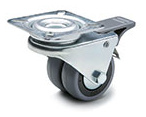
RE.C7-G
Twin castors for the general public with steel bracket
Vulcanised rubber coating
TX.
Plugs
Polyethylene
VCK.
Cam latches with knob
Steel or stainless steel cam
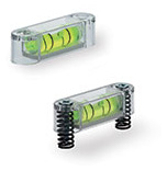
BOL-MB
Monodirectional screw-on levels
for screw mounting, technopolymer
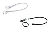
GN 111.2
Retaining Cables
Stainless Steel, with Key Rings or One Key Ring and One Mounting Tab / with Mounting Tabs or Loops
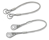
GN 111.8
Stainless Steel Retaining Cables
AISI 316, with Key Rings or One Key Ring and One Mounting Tab / with Mounting Tabs
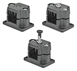
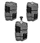
GN 810.12
Knee Lever Modules
Steel, to Screw-On
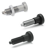
GN 618
Indexing plungers
without thread, without rest position
GN 147.7
Flanged Locking Slide Units
Aluminum
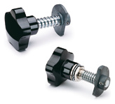
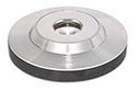
GN 6311.3
Foot Plates
for Grub Screws DIN 6332 / for Tommy Screws DIN 6304 / DIN 6306, Steel
GN 6311.5
Foot Plates
for Grub Screws DIN 6332, Stainless Steel
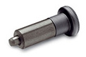
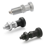
GN 617
Indexing plungers
Steel / Stainless Steel without rest position
GN 613
Indexing plungers
Steel / Stainless Steel without rest position
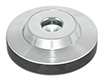
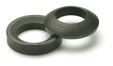
DIN 6319
Spherical / Dished Washers
Steel / Stainless Steel
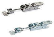
GN 761
Toggle latches
Steel / Stainless Steel, without lock mechanism
GN 343.3
Levelling feet
Foot plastic, female thread
GN 343.7
Levelling feet
Foot plastic / female thread Stainless Steel
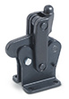
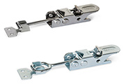
GN 761.1
Toggle latches
Steel / Stainless Steel, with lock mechanism
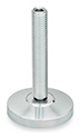
GN 6311.4
Leveling Feet
Steel
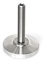
GN 6311.6
Leveling Feet
Stainless Steel
GN 134.7
Two-Way Locking Slide Units
Aluminum
<<
«
1
2
»
>>
ALL