 Technical datasheet
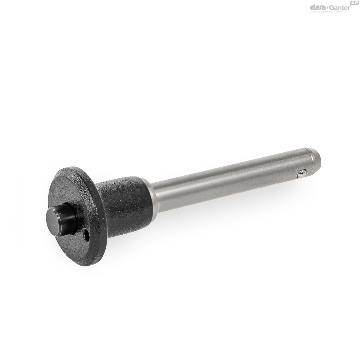
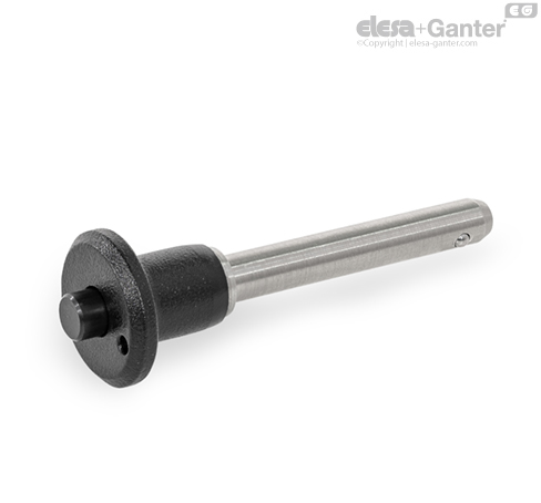
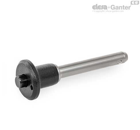
GN 113.20-PBall Lock Pins
With mushroom shaped handle
Stainless Steel, Handle Aluminum
GN 113.20-P
|
Catalogue
|
d1 -0.04/-0.08
|
l1 +0.6
|
d2
|
d3
|
d4
|
l2 ±1
|
l3
|
Location
bore H11 |
Load capacity F in kN≈
double sided shearing resistance acc. DIN 50141 (breaking strength) |
|
|---|---|---|---|---|---|---|---|---|---|---|
|
|
|
|
|
|
|
|
|
|
|
|
|
GN 113.20-5-10-P-C
|
5
|
10
|
5.5
|
11.3
|
20
|
6
|
17.6
|
5
|
24
|
12
|
|
GN 113.20-5-15-P-C
|
5
|
15
|
5.5
|
11.3
|
20
|
6
|
17.6
|
5
|
24
|
12
|
|
GN 113.20-5-20-P-C
|
5
|
20
|
5.5
|
11.3
|
20
|
6
|
17.6
|
5
|
24
|
13
|
|
GN 113.20-5-25-P-C
|
5
|
25
|
5.5
|
11.3
|
20
|
6
|
17.6
|
5
|
24
|
14
|
|
GN 113.20-5-30-P-C
|
5
|
30
|
5.5
|
11.3
|
20
|
6
|
17.6
|
5
|
24
|
15
|
|
GN 113.20-6-10-P-C
|
6
|
10
|
7
|
11.3
|
20
|
7
|
17.6
|
6
|
35
|
13
|
|
GN 113.20-6-15-P-C
|
6
|
15
|
7
|
11.3
|
20
|
7
|
17.6
|
6
|
35
|
14
|
|
GN 113.20-6-20-P-C
|
6
|
20
|
7
|
11.3
|
20
|
7
|
17.6
|
6
|
35
|
15
|
|
GN 113.20-6-25-P-C
|
6
|
25
|
7
|
11.3
|
20
|
7
|
17.6
|
6
|
35
|
16
|
|
GN 113.20-6-30-P-C
|
6
|
30
|
7
|
11.3
|
20
|
7
|
17.6
|
6
|
35
|
17
|
|
GN 113.20-6-35-P-C
|
6
|
35
|
7
|
11.3
|
20
|
7
|
17.6
|
6
|
35
|
18
|
|
GN 113.20-6-40-P-C
|
6
|
40
|
7
|
11.3
|
20
|
7
|
17.6
|
6
|
35
|
19
|
|
GN 113.20-6-45-P-C
|
6
|
45
|
7
|
11.3
|
20
|
7
|
17.6
|
6
|
35
|
20
|
|
GN 113.20-6-50-P-C
|
6
|
50
|
7
|
11.3
|
20
|
7
|
17.6
|
6
|
35
|
21
|
|
GN 113.20-8-20-P-C
|
8
|
20
|
9.5
|
14.1
|
25
|
8.2
|
22.6
|
8
|
63
|
29
|
|
GN 113.20-8-25-P-C
|
8
|
25
|
9.5
|
14.1
|
25
|
8.2
|
22.6
|
8
|
63
|
31
|
|
GN 113.20-8-30-P-C
|
8
|
30
|
9.5
|
14.1
|
25
|
8.2
|
22.6
|
8
|
63
|
33
|
|
GN 113.20-8-35-P-C
|
8
|
35
|
9.5
|
14.1
|
25
|
8.2
|
22.6
|
8
|
63
|
35
|
|
GN 113.20-8-40-P-C
|
8
|
40
|
9.5
|
14.1
|
25
|
8.2
|
22.6
|
8
|
63
|
36
|
|
GN 113.20-8-45-P-C
|
8
|
45
|
9.5
|
14.1
|
25
|
8.2
|
22.6
|
8
|
63
|
38
|
|
GN 113.20-8-50-P-C
|
8
|
50
|
9.5
|
14.1
|
25
|
8.2
|
22.6
|
8
|
63
|
40
|
|
GN 113.20-10-20-P-C
|
10
|
20
|
12
|
14.1
|
25
|
9.6
|
22.6
|
10
|
100
|
36
|
|
GN 113.20-10-25-P-C
|
10
|
25
|
12
|
14.1
|
25
|
9.6
|
22.6
|
10
|
100
|
38
|
|
GN 113.20-10-30-P-C
|
10
|
30
|
12
|
14.1
|
25
|
9.6
|
22.6
|
10
|
100
|
42
|
|
GN 113.20-10-35-P-C
|
10
|
35
|
12
|
14.1
|
25
|
9.6
|
22.6
|
10
|
100
|
44
|
|
GN 113.20-10-40-P-C
|
10
|
40
|
12
|
14.1
|
25
|
9.6
|
22.6
|
10
|
100
|
47
|
|
GN 113.20-10-45-P-C
|
10
|
45
|
12
|
14.1
|
25
|
9.6
|
22.6
|
10
|
100
|
50
|
|
GN 113.20-10-50-P-C
|
10
|
50
|
12
|
14.1
|
25
|
9.6
|
22.6
|
10
|
100
|
53
|
|
GN 113.20-10-60-P-C
|
10
|
60
|
12
|
14.1
|
25
|
9.6
|
22.6
|
10
|
100
|
59
|
|
GN 113.20-12-25-P-C
|
12
|
25
|
14.5
|
17.7
|
35
|
10.6
|
27.3
|
12
|
144
|
70
|
|
GN 113.20-12-30-P-C
|
12
|
30
|
14.5
|
17.7
|
35
|
10.6
|
27.3
|
12
|
144
|
75
|
|
GN 113.20-12-35-P-C
|
12
|
35
|
14.5
|
17.7
|
35
|
10.6
|
27.3
|
12
|
144
|
79
|
|
GN 113.20-12-40-P-C
|
12
|
40
|
14.5
|
17.7
|
35
|
10.6
|
27.3
|
12
|
144
|
83
|
|
GN 113.20-12-45-P-C
|
12
|
45
|
14.5
|
17.7
|
35
|
10.6
|
27.3
|
12
|
144
|
88
|
|
GN 113.20-12-50-P-C
|
12
|
50
|
14.5
|
17.7
|
35
|
10.6
|
27.3
|
12
|
144
|
92
|
|
GN 113.20-12-60-P-C
|
12
|
60
|
14.5
|
17.7
|
35
|
10.6
|
27.3
|
12
|
144
|
100
|
|
GN 113.20-12-70-P-C
|
12
|
70
|
14.5
|
17.7
|
35
|
10.6
|
27.3
|
12
|
144
|
109
|
|
GN 113.20-12-80-P-C
|
12
|
80
|
14.5
|
17.7
|
35
|
10.6
|
27.3
|
12
|
144
|
117
|
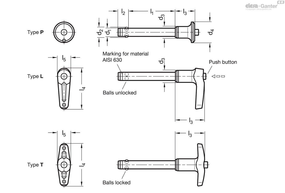
Types
Types
- Type P: With mushroom shaped handle
- Type L: With L-handle
- Type T: With T-handle
Pin
Pin
- Stainless steel AISI 303 A
- Stainless steel AISI 630 C
- Precipitation hardened
Balls
Balls
Stainless steel AISI 420C
Handle
Handle
Aluminum
Powder coated
Black, RAL 9005, textured finish
Pressure spring
Pressure spring
Stainless steel AISI 631
Operating temperature -30 °C to +150 °C
Operating temperature -30 °C to +150 °C
Ball lock pins GN 113.20 are used for quick fixing, connecting and locking of various parts and workpieces. A typical application is locating pins which have often to be removed and installed again.
The two balls are unlocked by pressing the spring-loaded button and locked again when released.
The hardened pin of version C has high wear resistance and tensile strength, making it suitable for applications involving heavy elements.
The technical appendix contains the load capacities for the double-sided shearing resistance (breaking strength).

Information
Information
The load capacities specified in the table for the double sided shearing resistance (breaking strength) have been calculated or theoretically defined on the basis of DIN 50141.
At the same time, the endangered bolt cross-section S, according to a nearby sketch, was considered in two shear planes before breakage.
The details given on load rating are non-binding guide values without any liability. In general, they do not constitute a warranty of condition.
The user must determine whether the product is suitable for the intended purpose. Environmental factors can influence the specified values.
An appropriate safety factor must be taken into account in the design.
Load capacity F in kN ≈ double sided shearing resistance acc. DIN 50141 (breaking strength)
Load capacity F in kN ≈ double sided shearing resistance acc. DIN 50141 (breaking strength)
Related products

DIN 172-ST
Guide Bushings
Steel / Stainless Steel, Drill Bushings, with Collar

DIN 179-ST
Guide Bushings
Steel / Stainless Steel, Drill Bushings, without Collar
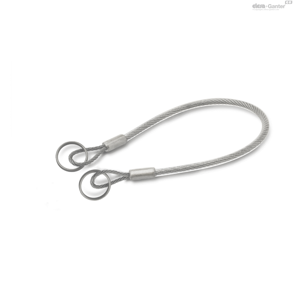
GN 111.8-A
Stainless Steel Retaining Cables
AISI 316, with Key Rings or One Key Ring and One Mounting Tab / with Mounting Tabs
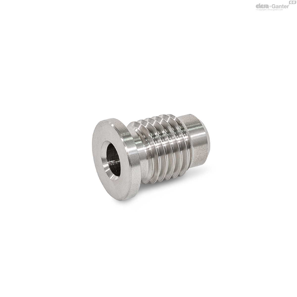
GN 1140-B
Holding Bushings
Stainless Steel, for Ball Lock Pins / Locking Pins